Clamp

A fixture and operating handle technology, applied in the field of metallurgical fixture manufacturing, can solve the problems of inability to use fixture equipment, small size of melting furnace, poor operation convenience, etc.

Pending Publication Date: 2021-08-31
SHANDONG IRON & STEEL CO LTD
View PDF0 Cites 0 Cited by
  • Summary
  • Abstract
  • Description
  • Claims
  • Application Information

AI Technical Summary

Problems solved by technology

In the aforementioned process, the size of the smelting furnace of the smelting equipment is small, and the fixture equipment used in the factory in the prior art cannot be used. However, the fixtures currently used are simple in structure and usually only have basic clamping functions, so the operation is not convenient and safe. low reliability, it is difficult to accurately and quickly complete the steel-loading operation of the melting furnace

Method used


Image

  • Clamp
  • Clamp
  • Clamp

Examples


Embodiment Construction

[0029] The following will clearly and completely describe the technical solutions in the embodiments of the present invention with reference to the accompanying drawings in the embodiments of the present invention. Obviously, the described embodiments are only some, not all, embodiments of the present invention. Based on the embodiments of the present invention, all other embodiments obtained by persons of ordinary skill in the art without making creative efforts belong to the protection scope of the present invention.

[0030] In order to enable those skilled in the art to better understand the solution of the present invention, the present invention will be further described in detail below in conjunction with the accompanying drawings and specific embodiments.

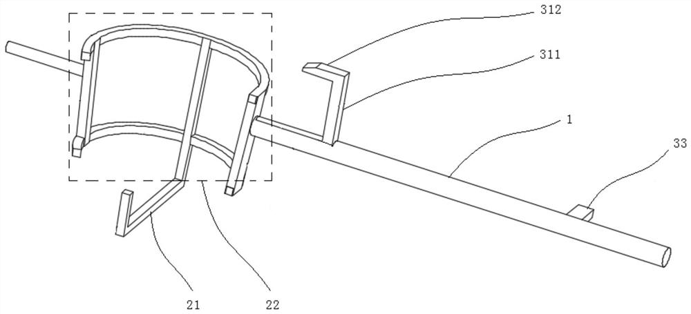
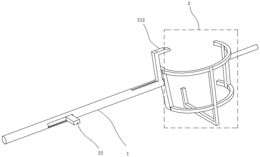
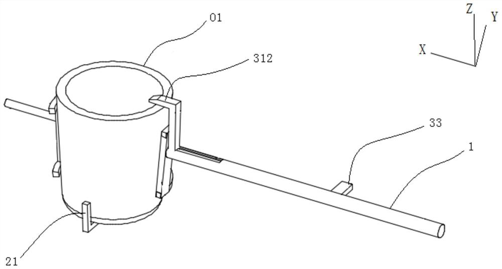
[0031] Please refer to Figure 1 to Figure 7 , figure 1 A schematic structural view of the fixture in the first direction provided for the embodiment of the present invention; figure 2 Schematic diagram of the st...


PUM


Abstract

The invention discloses a clamp. The clamp comprises a first operation handle and a claw arranged on the first operation handle and used for lifting a workpiece to be clamped, wherein the first operation handle is slidably or rotatably connected with a second operation handle, the end of the second operation handle is provided with a pressing claw used for pressing a workpiece to be clamped downwards when the pressing claw moves to the position above the claw, an operator can clamp and move the workpiece to be clamped such as a smelting furnace through the clamp, and when the smelting furnace is grabbed or unloaded, the clamp can quickly realize taking and placing of the smelting furnace through the claw hands; and when molten steel in the smelting furnace is clamped and poured out, the clamp restrains the smelting furnace through the claw and the pressing claw at the same time, it is guaranteed that the smelting furnace is stably fixed in the space defined by the claw and the pressing claw in the pitching process of the furnace opening of the smelting furnace, and operation safety is guaranteed. The clamp is light in overall weight, simple in structure and low in cost, and the steel discharging process can be independently completed without other auxiliary equipment.

Description

technical field [0001] The invention relates to the technical field of metallurgical fixture manufacturing, in particular to a fixture. Background technique [0002] In the laboratory, melting equipment with the principle of electromagnetic induction heating is usually used to complete the secondary melting of some metals. In the aforementioned process, the smelting furnace of the smelting equipment is small in size, and the fixture equipment used in the factory in the prior art cannot be used. However, the fixtures currently used are simple in structure and usually only have basic clamping functions, so the operation is not convenient and safe. Low reliability, it is difficult to accurately and quickly complete the steel-putting operation of the smelting furnace. [0003] For this reason, how to provide a clamp that is convenient for manual operation and can be used for clamping and moving the melting furnace conveniently, quickly, safely and reliably has become an urgent ...

Claims


Application Information

Patent Timeline
Patent Type & Authority Applications(China)
IPC IPC(8): B25J1/04
CPCB25J1/04
Inventor 方金林孙晓庆
Owner SHANDONG IRON & STEEL CO LTD
Why Eureka
Try Eureka