

Fabricated connecting joint of steel truss bridge
A joint connection and assembly technology, which is applied in truss bridges, bridge forms, erection/assembly bridges, etc., can solve problems affecting the service life of steel structure bridges, difficulty in disassembling connecting plates, and inability to adjust the inclination angle of inclined beams, etc., to achieve strengthening The effect of bearing capacity and compact structure
- Summary
- Abstract
- Description
- Claims
- Application Information
AI Technical Summary
Problems solved by technology
Method used
Image

Examples
Embodiment 1
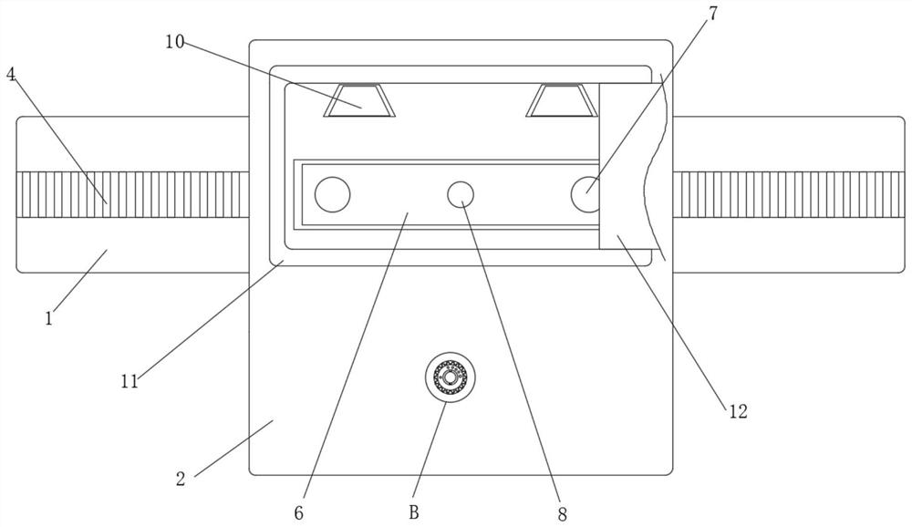
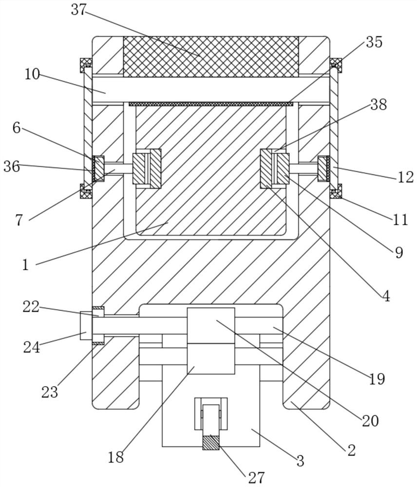
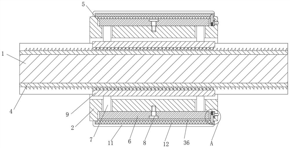
[0044] Such as figure 1 A steel truss bridge assembly type connection node shown in -7 includes a node connection plate 2 that is sleeved on the outer side of the transverse beam 1 and opens upward. The beam 3 and the node connection plate 2 are slidingly connected with a plurality of trapezoidal load-bearing plates 10 arranged in horizontal rows and located on the top of the transverse beam 1. There are two symmetrical grooves 38 in the transverse beam 1. One side of the groove 38 The inner wall is fixedly connected with a first locking tooth 4, two groups of fixing components are symmetrically arranged in the node connecting plate 2 for fixing the transverse beam 1, and the node connecting plate 2 is provided with an adjustment component for adjusting the inclination angle of the node connecting plate 2, The tops of the two inclined beams 3 are fixedly provided with semi-scalloped rings 21 , and the inner walls on both sides of the bottom of the node connection plate 2 are f...
Embodiment 2
[0053] This embodiment is a further improvement of the previous embodiment, such as figure 1 As shown in -10, a steel truss bridge assembly type connection node includes a node connection plate 2 that is sleeved on the outer side of the transverse beam 1 and opens upward. The beam 3 and the node connection plate 2 are slidingly connected with a plurality of trapezoidal load-bearing plates 10 arranged in horizontal rows and located on the top of the transverse beam 1. There are two symmetrical grooves 38 in the transverse beam 1. One side of the groove 38 The inner wall is fixedly connected with a first locking tooth 4, two groups of fixing components are symmetrically arranged in the node connecting plate 2 for fixing the transverse beam 1, and the node connecting plate 2 is provided with an adjustment component for adjusting the inclination angle of the node connecting plate 2, The tops of the two inclined beams 3 are fixedly provided with semi-scalloped rings 21 , and the in...
PUM
 Abstract
Description
Claims
Application Information