
Automatic cutting mechanism for flat iron angle steel for manufacturing fan

A technology of automatic cutting and flat iron, applied in the direction of manufacturing tools, metal sawing equipment, sawing machine, etc., can solve the problems affecting production efficiency, difficult to meet the processing needs of continuous cutting and mass production, and manual retrieving, to achieve Guarantee cutting accuracy and cutting quality, improve cutting processing efficiency, and stabilize the cutting process

Active Publication Date: 2021-09-03
南通维益机电有限公司
View PDF6 Cites 0 Cited by
  • Summary
  • Abstract
  • Description
  • Claims
  • Application Information

AI Technical Summary

Problems solved by technology

[0002] Some parts that need to be used in the production and processing of fans usually need to be made of angle steel or flat iron, and the angle steel and flat iron need to be cut to cut the parts to the required size. However, the existing angle steel cutting usually requires manual labor. Cutting, during cutting, workers need to manually fix the angle steel. After cutting the angle steel into the required length, the whole cutting process is more complicated, so the efficiency is low, and the stability of the worker's manual cutting process is poor, so the cutting accuracy is low and the quality is low. Poor, at the same time, after cutting, it needs to manually pick up and unload the material, which affects the production efficiency, and it is difficult to meet the processing needs of continuous cutting and mass production

Method used


Image

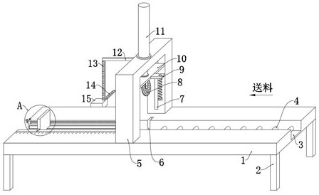
  • Automatic cutting mechanism for flat iron angle steel for manufacturing fan
  • Automatic cutting mechanism for flat iron angle steel for manufacturing fan
  • Automatic cutting mechanism for flat iron angle steel for manufacturing fan

Examples


Embodiment Construction

[0026] The following will clearly and completely describe the technical solutions in the embodiments of the present invention with reference to the drawings in the embodiments of the present invention.

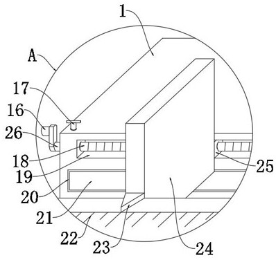
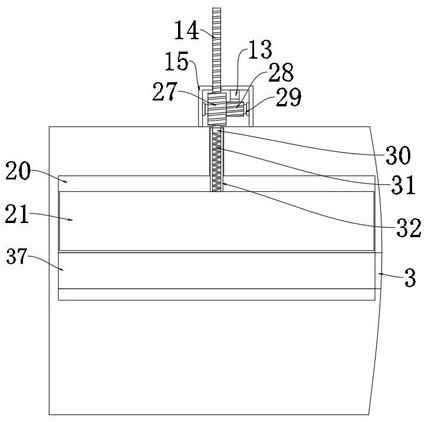
[0027] refer to Figure 1-6 , a flat iron angle steel automatic cutting mechanism for manufacturing fans, comprising a cutting table 1, and the bottom of the cutting table 1 is provided with a leg 2, the upper end of the cutting table 1 is provided with a feeding groove 3 along the feeding direction, and the upper end of the cutting table 1 is provided with There is a mounting frame 5 positioned above the feeding trough 3, the top of the mounting frame 5 is provided with a lifting cylinder 11, and the telescoping end of the lifting cylinder 11 penetrates the mounting frame 5 downwards and is fixed with a mobile seat 10. The inner wall of the mounting frame 5 is provided with a The guide groove 7 that the moving seat 10 is adapted to, the two ends of the moving seat 10 are prov...


PUM


Abstract

The invention discloses an automatic cutting mechanism for flat iron angle steel for manufacturing a fan. The automatic cutting mechanism comprises a cutting table, the bottom of the cutting table is provided with supporting legs, the upper end of the cutting table is provided with a feeding groove in the feeding direction, the upper end of the cutting table is provided with a mounting frame located above the feeding groove, and the top of the mounting frame is provided with a lifting oil cylinder. The telescopic end of the lifting oil cylinder downwards penetrates through the mounting frame and is fixedly provided with a moving seat, a cutting knife is arranged at the lower end of the moving seat, fixing mechanisms used for fixing angle steel are arranged on the two sides of the moving seat correspondingly, a material blocking mechanism used for limiting the angle steel is arranged on the left side of the interior of the feeding groove, and a discharging opening is formed in the inner bottom wall of the left side of the feeding groove. According to the automatic cutting mechanism for the flat iron angle steel for manufacturing the fan, the cutting process is stable, the cutting precision and the cutting quality are guaranteed, flexible adjustment can be conducted according to cutting needs, meanwhile, the cutting machining efficiency is high, the machining needs of continuous cutting are met, and the cutting mechanism is suitable for mass production.

Description

technical field [0001] The invention relates to the technical field of fan manufacturing, in particular to an automatic cutting mechanism for flat iron angle steel used for manufacturing a fan. Background technique [0002] Some parts that need to be used in the production and processing of fans usually need to be made of angle steel or flat iron, and the angle steel and flat iron need to be cut to cut the parts to the required size. However, the existing angle steel cutting usually requires manual labor. Cutting, during cutting, workers need to manually fix the angle steel. After cutting the angle steel into the required length, the whole cutting process is more complicated, so the efficiency is low, and the stability of the worker's manual cutting process is poor, so the cutting accuracy is low and the quality is low. Poor, at the same time, after cutting, it needs to manually take and unload the material, which affects the production efficiency, and it is difficult to mee...

Claims


Application Information

Patent Timeline
Patent Type & Authority Applications(China)
IPC IPC(8): B23D47/04
CPCB23D47/042B23D47/04
Inventor 姜小波
Owner 南通维益机电有限公司
Learn More