Terminal self-adaption method in personnel positioning system and system thereof

A personnel positioning and self-adaptive technology, applied in the field of personnel positioning, it can solve the problems of high (such as public office areas, conference rooms, personnel positioning systems are not flexible enough, and the flow of people is small), so as to improve the channel utilization rate and widen the positioning range , the effect of low power consumption

Active Publication Date: 2021-09-03
HANGZHOU KONKE INFORMATION TECH CO LTD
View PDF6 Cites 0 Cited by
  • Summary
  • Abstract
  • Description
  • Claims
  • Application Information

AI Technical Summary

Problems solved by technology

However, the above scheme still has obvious shortcomings. For example, the above-mentioned personnel positioning system is not flexible enough, and the portable terminal sends messages to the gateway in the same way no matter where it is. However, in practical applications, the area of ​​a positioning system usually includes multiple Areas with different characteristics, some areas are vast but have less traffic (such as automated workshops), and some areas have relatively large traffic and high busyness (such as public office areas, conference rooms, etc.). In addition, a positioning system may span Several remote areas, such as construction sites and office areas, users walk back and forth in these areas with different levels of busyness. If the low-speed transmission mode is fixed, it will cause message conflicts and network congestion in high-busy areas. Fixed high-speed transmission mode will result in the inability to achieve precise positioning in a wide range of areas, and more gateways must be used, which will lead to a substantial increase in costs. The larger the system coverage area, the greater the cost increase
In order to solve the aforementioned problems, some companies have thought of adopting a compromise medium-speed transmission method, but this method cannot achieve the best results to the greatest extent.

Method used


Image

  • Terminal self-adaption method in personnel positioning system and system thereof
  • Terminal self-adaption method in personnel positioning system and system thereof
  • Terminal self-adaption method in personnel positioning system and system thereof

Examples


Embodiment 1

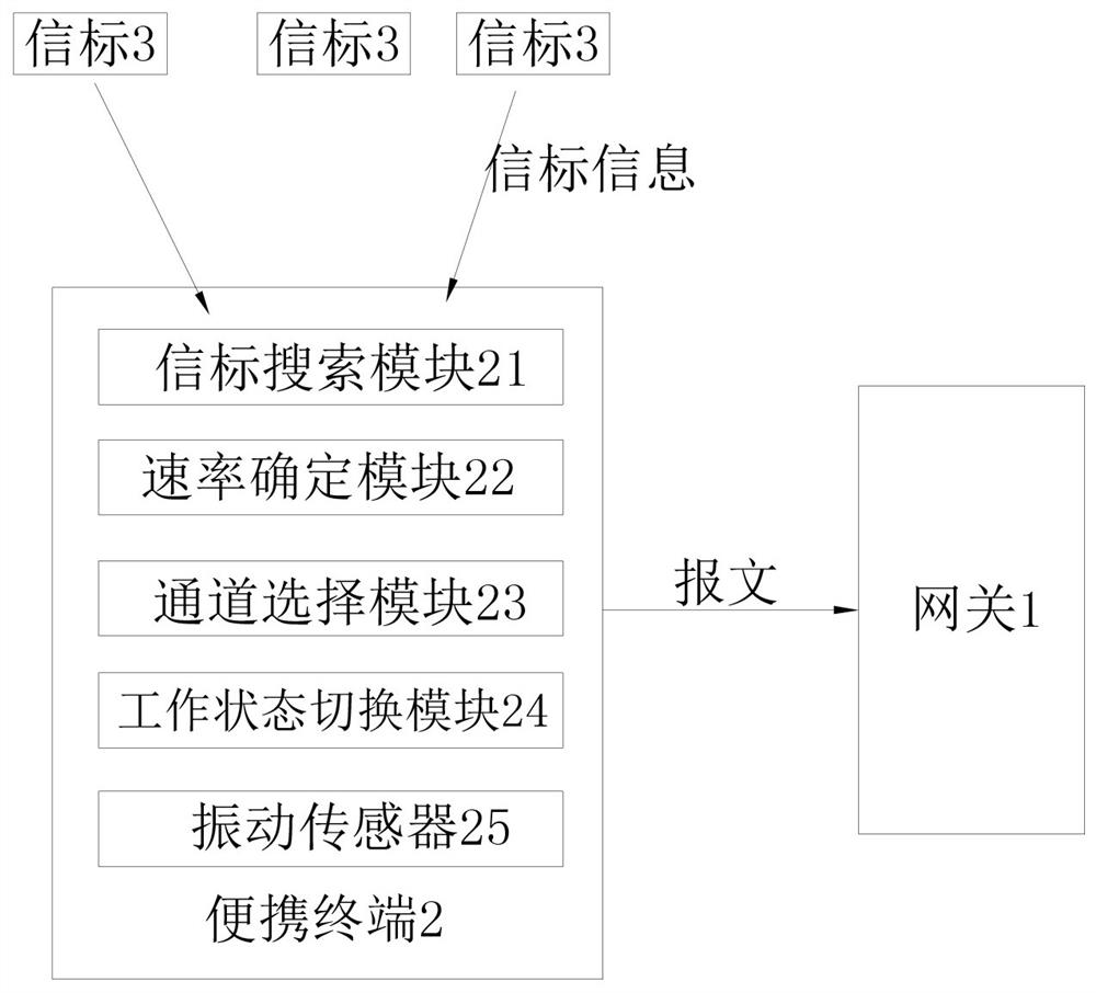
[0062] Such as figure 1 As shown, this embodiment discloses a terminal adaptive method in a personnel positioning system and a personnel positioning system based on the terminal adaptive method. Among them, the personnel positioning system includes one or more gateways 1 arranged in the area to be positioned, portable terminals 2 for users to carry, and beacons 3 grids arranged on the ground. The portable terminals 2 can be special terminals such as badges and badges, It can also be integrated into portable devices such as bracelets and mobile phones.

[0063] Preferably, the gateway 1 of this embodiment has multiple channels. Portable terminal 2 comprises beacon search module 21, rate determination module 22, channel selection module 23, working status switching module 24 and vibration sensor 25, and beacon search module 21 is used for searching beacon information, and rate determination module 22 is used for according to signal The beacon information determines the transmi...

Embodiment 2

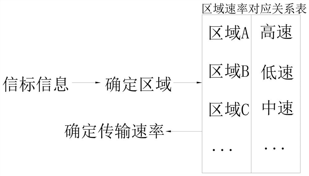
[0097] This embodiment is similar to Embodiment 1, the difference is that the corresponding relationship of each area, transmission rate and gateway in this embodiment is stored in the portable terminal 2, such as Figure 6 As shown, the portable terminal 2 determines the current area according to the beacon information, then determines the transmission rate according to the current area, and at the same time determines the gateway 1 to send the message according to the current area. In practical applications, there may be cases where areas with different speeds are adjacent, so it is possible that the positioning position of the portable terminal is in a certain high-speed area, but due to the gateway layout, location proximity, etc., the portable terminal is closer to the low-speed gateway in the low-speed area , at this time, it is prone to the problem of sending packets directly to the low-speed gateway, resulting in unsuccessful sending. In this embodiment, the relationsh...

Embodiment 3

[0100] This embodiment is similar to Embodiment 1, but the method of determining the rate is different from Embodiment 1. In this embodiment, according to the area where the beacon 3 is located, the corresponding beacon information is embedded in the transmission rate in advance. In step S2, the portable Terminal 2 directly determines the transmission rate from the searched beacon information. When the portable terminal 2 searches for a plurality of beacon information, and the plurality of beacon information carry different transmission rates, the transmission rate in the first searched beacon information is taken as the final transmission rate.

[0101] Preferably, the beacon information can carry the gateway information of the gateways in the corresponding area at the same time, so that the portable terminal 2 can quickly determine the gateway as the message sending object. When there are multiple gateways in an area, the portable terminal selects the nearest gateway as the g...


PUM


Abstract

The invention discloses a terminal self-adaption method in a personnel positioning system and a system thereof. The terminal self-adaption method comprises a rate self-adaption method, wherein the rate self-adaption method comprises the following steps of: S1, searching beacon information by a portable terminal; S2, determining a transmission rate according to the beacon information; and S3, sending the message containing the beacon information to the gateway at the transmission rate determined in the step S2. The portable terminal can adapt to the transmission rate according to the characteristics of the position where the portable terminal is located, the positioning distance of the positioning system is increased, the positioning precision of the system is guaranteed, the arrangement cost of the gateway can be reduced and the system performance can be optimized to the maximum extent while the requirements of all areas are met, and the method has obvious advantages compared with a fixed-rate scheme in the prior art.

Description

technical field [0001] The invention belongs to the technical field of personnel positioning, and in particular relates to a terminal self-adaptation method in a personnel positioning system and a system thereof. Background technique [0002] The basic structure of the traditional personnel positioning system is fixed deployment of positioning base stations, personnel carry positioning tags, and the positioning base station receives information from the positioning tags carried by personnel, and performs identification and positioning according to its field strength, phase, tag serial code and other information. This architecture has disadvantages such as complex system, complex positioning and easy environmental impact on positioning accuracy. [0003] In order to solve the above technical problems, people have carried out long-term exploration, such as a personnel positioning system disclosed in a Chinese patent [application number: CN201310684121.8], including a personnel...

Claims


Application Information

Patent Timeline
Patent Type & Authority Applications(China)
IPC IPC(8): H04W64/00H04W52/02H04W4/021
CPCH04W64/00H04W64/006H04W52/0261H04W4/021Y02D30/70
Inventor 赵元表丁明正金强敏
Owner HANGZHOU KONKE INFORMATION TECH CO LTD
Why Eureka
Try Eureka