
Sand screening machine for construction site

A technology of construction site and sand screening machine, which is applied in the direction of screening, solid separation, grille, etc., can solve the problems of not easy screening, reducing sand screening effect, and blocking meshes by foreign objects.

Inactive Publication Date: 2021-09-10
魏丽爱
View PDF0 Cites 0 Cited by
  • Summary
  • Abstract
  • Description
  • Claims
  • Application Information

AI Technical Summary

Problems solved by technology

[0003] In view of the deficiencies in the prior art, the purpose of the present invention is to provide a construction site sand sieving machine with the function of dredging the mesh of the cylindrical screen, so as to solve the problem that the existing sand sieving machine will have some problems when screening sand. Stones and other foreign objects slightly larger than the mesh of the cylindrical screen block the mesh, and the accumulated sand is not easy to screen after agglomeration, which will cause the whole block to be screened out and reduce the sand screening effect.

Method used


Image

  • Sand screening machine for construction site
  • Sand screening machine for construction site
  • Sand screening machine for construction site

Examples


Embodiment 1

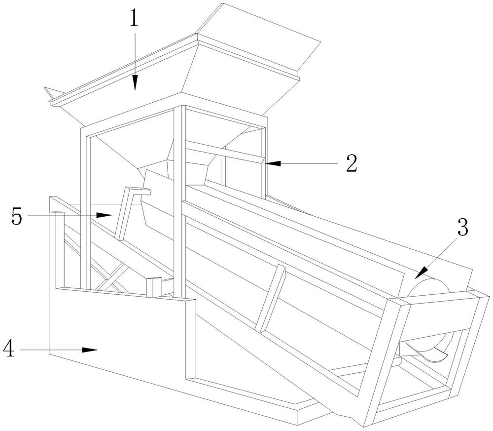
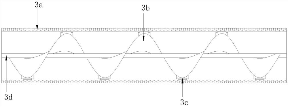
[0027] see Figure 1-2 , the present invention provides a sand screening machine for construction sites, the structure of which includes a sand feeding bin 1, a frame 2, a sand screening device 3, a base 4, and a conveyor belt 5, the sand feeding bin 1 is fixed on the top of the frame 2, and the The frame 2 is installed on the base 4, the base 4 is connected to the conveyor belt 5, the sand screening device 3 is connected to the frame 2, and the sand screening device 3 includes a cylindrical screen 3a, an auger 3b, and a dredging mechanism 3c , a rotating shaft 3d, the inside of the cylindrical screen 3a is provided with a rotating shaft 3d, the rotating shaft 3d is connected with the auger 3b, and a dredging mechanism 3c is installed on the auger 3b.

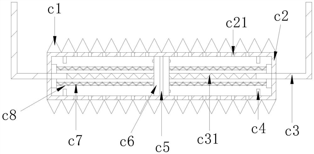
[0028] see Figure 3-4 , the dredging mechanism 3c includes a conical block c1, a mechanism body c2, a fixed rod c3, a buffer ring c4, a partition c5, a push plate c6, a tension spring c7, and a fixed telescopic rod c8, and th...

Embodiment 2

[0031] see Figure 1-2 , the present invention provides a sand screening machine for construction sites, the structure of which includes a sand feeding bin 1, a frame 2, a sand screening device 3, a base 4, and a conveyor belt 5, the sand feeding bin 1 is fixed on the top of the frame 2, and the The frame 2 is installed on the base 4, the base 4 is connected to the conveyor belt 5, the sand screening device 3 is connected to the frame 2, and the sand screening device 3 includes a cylindrical screen 3a, an auger 3b, and a dredging mechanism 3c , a rotating shaft 3d, the inside of the cylindrical screen 3a is provided with a rotating shaft 3d, the rotating shaft 3d is connected with the auger 3b, and a dredging mechanism 3c is installed on the auger 3b.

[0032] see Figure 3-4 , the dredging mechanism 3c includes a conical block c1, a mechanism body c2, a fixed rod c3, a buffer ring c4, a partition c5, a push plate c6, a tension spring c7, and a fixed telescopic rod c8, and th...


PUM


Abstract

The invention discloses a sand screening machine for a construction site. The sand screening machine structurally comprises a sand inlet bin (1), a frame (2), a sand screening device (3), a base (4) and a conveyor belt (5), wherein the sand inlet bin (1) is fixed to the top of the frame (2), the frame (2) is installed on the base (4), the base (4) is connected with the conveyor belt (5), and the sand screening device (3) is connected with the frame (2). The sand screening device has the beneficial effects that meshes of a cylindrical screen are dredged through conical blocks, the meshes are prevented from being blocked by foreign matter such as pebbles, meanwhile, in the rolling process of a mechanism body, caked sand can be rolled and separated, meanwhile, the caked sand can be separated through rotation of a packing auger, and air flow sprayed out of an air outlet can clean the sand screening mechanism and can also play a role in dredging the meshes at the same time.

Description

technical field [0001] The invention relates to the field of construction machinery, in particular to a sand screening machine for a construction site. Background technique [0002] In construction, sand is widely used. The thickness of the sand itself is different, and due to the differences in the storage environment of the sand, it often contains large particles of impurities such as shells, plastics, and stones. It is easy to agglomerate after being damp during the accumulation process. Therefore, it is necessary to screen the sand according to the specific engineering needs when using it, and select sand with a suitable particle size as the material to achieve the required characteristics of concrete and other materials and ensure the construction quality. The existing When the sand screening machine screens the sand, there will be some foreign matter such as stones slightly larger than the cylindrical screen mesh to block the mesh, and the accumulated sand is not easy ...

Claims


Application Information

Patent Timeline
IPC IPC(8): B07B1/20B07B1/50B07B1/55
CPCB07B1/20B07B1/50B07B1/55
Inventor 魏丽爱
Owner 魏丽爱
Learn More