Compression pipe forming method
A technology for forming tubes and forming cavities, which is applied in the field of technology and can solve the problems of uneven deformation and uneven unevenness of tube blanks
- Summary
- Abstract
- Description
- Claims
- Application Information
AI Technical Summary
Problems solved by technology
Method used
Image
Examples
Embodiment 1
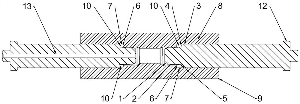
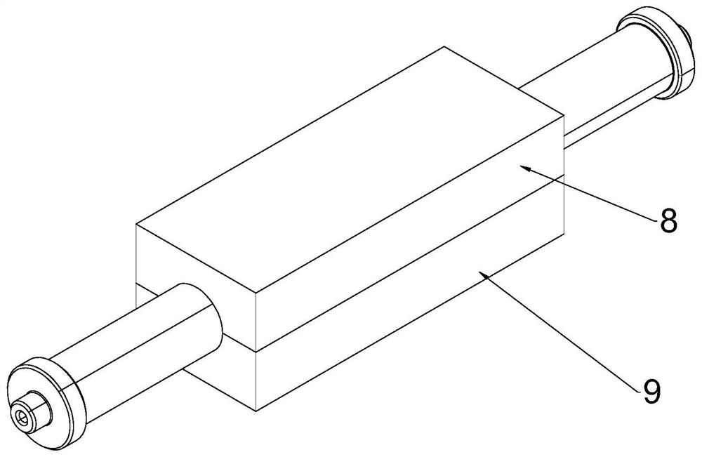
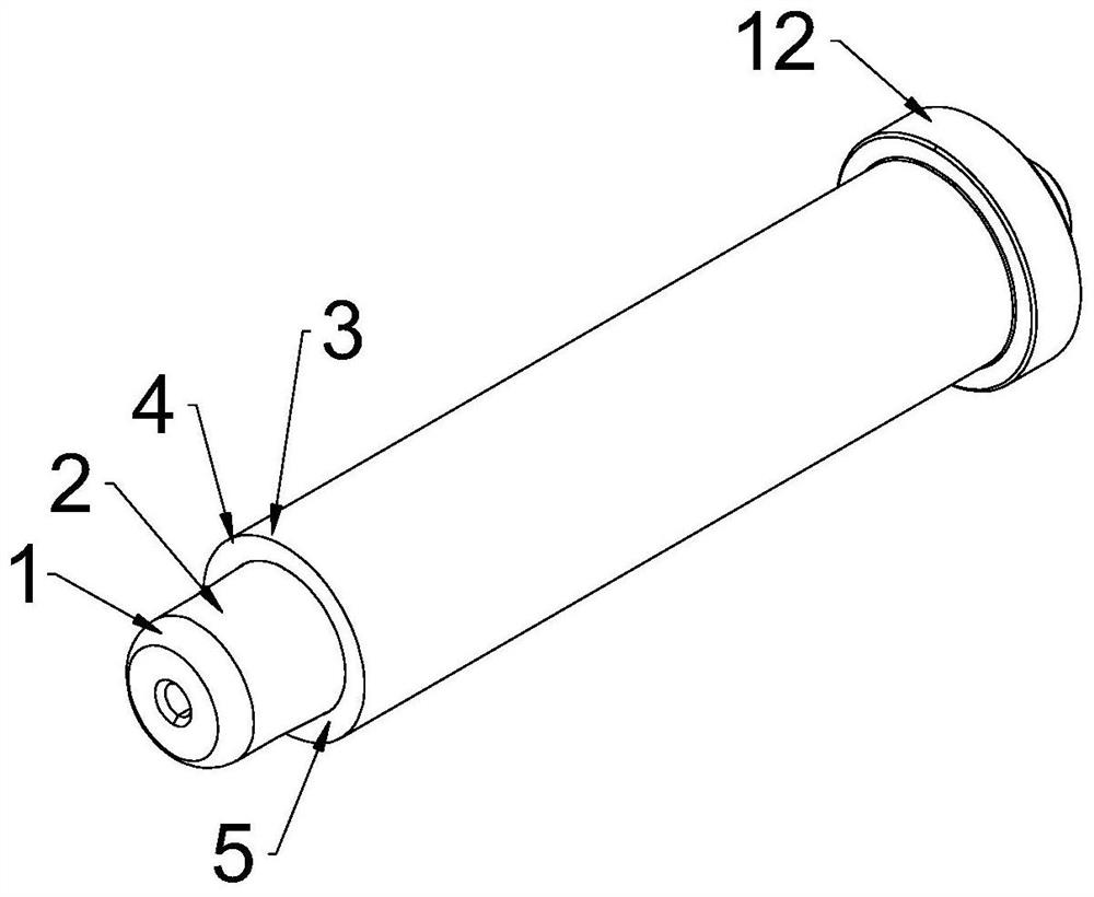
[0032] see Figure 1-Figure 3 , a pressing tube forming device, comprising a mold and punches arranged on both sides of the mold, the mold is provided with a cavity matching the appearance of the pressing tube, and the cavity includes a mold for forming the pressing tube The forming part of the sealed tube body; the punch includes a flaring section 1 for easy entry into the tube blank, a low-pressure sealing section 2 for low-pressure pre-expansion of the tube blank, and a high-pressure expansion type for the tube blank. The high-pressure sealing section 5 and the annular body 3 connected with the high-pressure sealing end; the high-pressure sealing section 5 includes a molding surface 4, and the molding surface 4 is located at the front end of the annular body 3, and it is characterized in that the molding surface 4 and the molding The part forms a rectangular molding cavity 10.
[0033] see Figure 1-Figure 3 , the forming portion includes a radial forming surface 6 arrang...
Embodiment 2
[0042] see Figure 4-Figure 5 The difference between this embodiment and Embodiment 1 is that an annular accommodation groove 11 for accommodating the end of the tube blank is formed between the low-pressure sealing section 2 and the high-pressure sealing section 5, and the annular body 3 corresponds to the annular accommodation groove 11. The groove 11 surrounds the low-pressure sealing section 2 , and the forming surface 4 is arranged at the front end of the annular body 3 . The annular accommodation groove 11 of the above-mentioned structure is provided. When forming the double-card press tube, the end of the tube blank is inserted into the annular accommodation groove 11 and pressed against the bottom of the annular accommodation groove 11. Since the forming surface 4 is located at the front end of the annular body 3, After the forming surface 4 is in place, there is a certain distance between the end of the tube blank and the circular arc cavity, so there is an end distan...
PUM
 Abstract
Description
Claims
Application Information
 - R&D
- Intellectual Property
- Life Sciences
- Materials
- Tech Scout
- Unparalleled Data Quality
- Higher Quality Content
- 60% Fewer Hallucinations
Browse by: Latest US Patents, China's latest patents, Technical Efficacy Thesaurus, Application Domain, Technology Topic, Popular Technical Reports.
© 2025 PatSnap. All rights reserved.Legal|Privacy policy|Modern Slavery Act Transparency Statement|Sitemap|About US| Contact US: help@patsnap.com


