
A kind of compression tube forming method

A technology for tube pressing and forming cavity, applied in the field of technology, can solve problems such as unevenness and uneven deformation of tube blanks, and achieve the effects of high shape accuracy, natural and smooth bending forming, and reducing requirements.

Active Publication Date: 2022-07-12
佛山市永恒液压机械有限公司
View PDF9 Cites 0 Cited by
  • Summary
  • Abstract
  • Description
  • Claims
  • Application Information

AI Technical Summary

Problems solved by technology

[0003] 1. When the tube blank is deformed, it is constantly restricted by the circular arc cavity, resulting in uneven deformation of the tube blank, and there is a problem of unevenness

Method used


Image

  • A kind of compression tube forming method
  • A kind of compression tube forming method
  • A kind of compression tube forming method

Examples


Embodiment 1

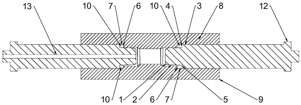
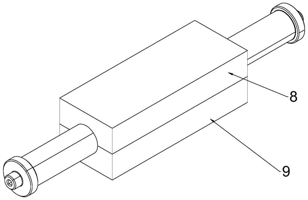
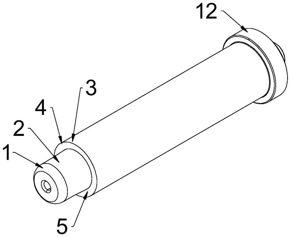
[0032] see Figure 1-Figure 3 , A compression tube forming device, comprising a mold and punches arranged on both sides of the mold, the mold is provided with a cavity matching the appearance of the compression tube, and the cavity includes a cavity for forming a compression tube. The forming part of the sealed tube body; the punch includes a flared section 1 for easy entry into the tube blank, a low-pressure sealing section 2 for low-pressure pre-expansion of the tube blank, and a high-pressure expansion type for the tube blank. The high-pressure sealing section 5 and the annular body 3 connected with the high-pressure sealing end; the high-pressure sealing section 5 includes a forming surface 4, and the forming surface 4 is located at the front end of the annular body 3, and is characterized in that the forming surface 4 is connected with the forming surface 4. The part forms a rectangular molding cavity 10 .

[0033] see Figure 1-Figure 3 , the forming part includes a ra...

Embodiment 2

[0042] see Figure 4-Figure 5 The difference between this embodiment and Embodiment 1 is that an annular accommodating groove 11 for accommodating the end of the tube blank is formed between the low-pressure sealing section 2 and the high-pressure sealing section 5, and the annular body 3 corresponds to the annular accommodating groove 11. The groove 11 surrounds the low-pressure sealing section 2 , and the forming surface 4 is arranged at the front end of the annular body 3 . The annular accommodating groove 11 of the above structure is provided. When forming the double-clamping tube, the end of the tube blank is embedded in the annular accommodating groove 11 and abuts the bottom of the annular accommodating groove 11. Since the forming surface 4 is located at the front end of the annular body 3, After the forming surface 4 is in place, there is a distance between the end of the tube blank and the annular circular arc cavity, so there is a distance between the forming positi...


PUM


Abstract

The invention discloses a pressing tube forming method, which comprises the following steps: (1) transporting the tube blank to be processed on the fixed die; (2) driving the movable die to move in the direction of the fixed die to complete the movable die and the fixed die (3) Drive the punches on both sides into the inner cavity of the tube blank from both ends of the tube blank, and perform low-pressure pre-expansion on the tube blank; (4) Drive the two punches to continue to move toward each other, so that the high-pressure sealing section The root part is pressed against the end of the tube blank; (5) the rectangular forming cavity is close to the two bottom corners of the tube blank and pressed against the tube blank, and the high-pressure liquid medium is passed in, so that the tube blank located between the two bottom corners of the forming cavity is formed. The direction of the cavity is naturally and smoothly bent and formed; (6) the high-pressure liquid medium continues to be introduced, so that the tube blank is continuously deformed in the forming cavity, and when the top of the forming cavity is resisted, the forming of the sealed tube body is completed. The compression tube forming method of the invention can make the tube blank more smooth and natural in the deformation process, and the shape precision is high.

Description

technical field [0001] The invention relates to a process method, in particular to a method for forming a pinched tube. Background technique [0002] Internal high-pressure forming is an advanced manufacturing technology for manufacturing hollow integral components. Seal both ends of the pipe with a punch, and use the axial feed to provide supplementary material for the forming of the pipe, so that the outer wall of the pipe is completely close to the mold cavity, so as to obtain parts of the desired shape. The compression tube is mainly formed by internal high pressure forming. The compression tube includes a sealing tube body arranged at the end. The sealing tube body is a radially outward protrusion. The cavity of the mold includes a sealing tube for forming a seal The annular arc cavity of the tube body; the existing punch includes a low-pressure sealing section for pre-expanding the tube blank with low pressure, a high-pressure sealing section for performing high-press...

Claims


Application Information

Patent Timeline
Patent Type & Authority Patents(China)
IPC IPC(8): B21D26/033B21D26/047B21D51/00
CPCB21D26/033B21D26/047B21D51/00
Inventor 罗荣斌胡红侯杰
Owner 佛山市永恒液压机械有限公司
Learn More