Method of manufacturing micro lens, micro lens, optical device, optical transmitting device, laser printer head, and laser printer

a manufacturing method and technology of micro lenses, applied in the direction of instruments, coatings, domestic applications, etc., can solve the problems of difficult to enhance the landing position accuracy of droplets, and achieve the effect of excelling in drawing characteristics

Inactive Publication Date: 2005-03-17
SEIKO EPSON CORP
View PDF16 Cites 18 Cited by
  • Summary
  • Abstract
  • Description
  • Claims
  • Application Information

AI Technical Summary

Benefits of technology

[0039] According to the laser printer, since it has a laser printer head having the proper drawin

Problems solved by technology

However, such a method involves a problem in that it is difficult to enhance the accuracy of

Method used


Image

  • Method of manufacturing micro lens, micro lens, optical device, optical transmitting device, laser printer head, and laser printer
  • Method of manufacturing micro lens, micro lens, optical device, optical transmitting device, laser printer head, and laser printer
  • Method of manufacturing micro lens, micro lens, optical device, optical transmitting device, laser printer head, and laser printer

Examples


first exemplary embodiment

[0051] A first exemplary embodiment of the present invention will now be described below with reference to FIGS. 1 through 8.

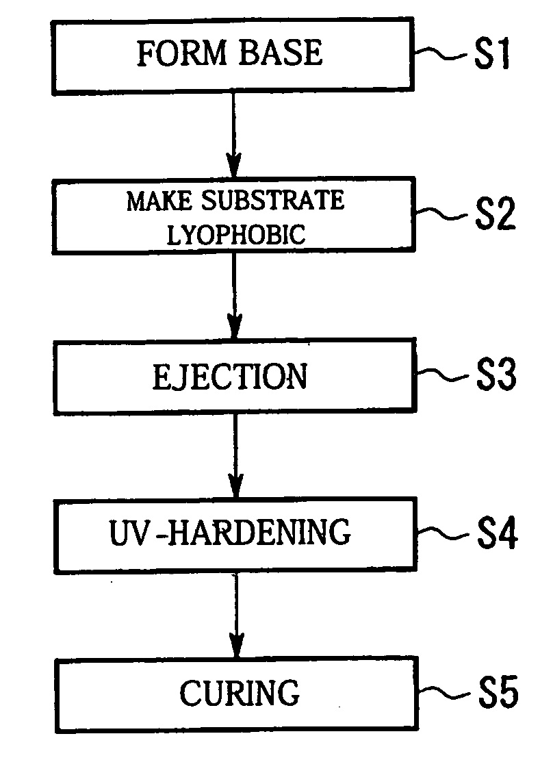
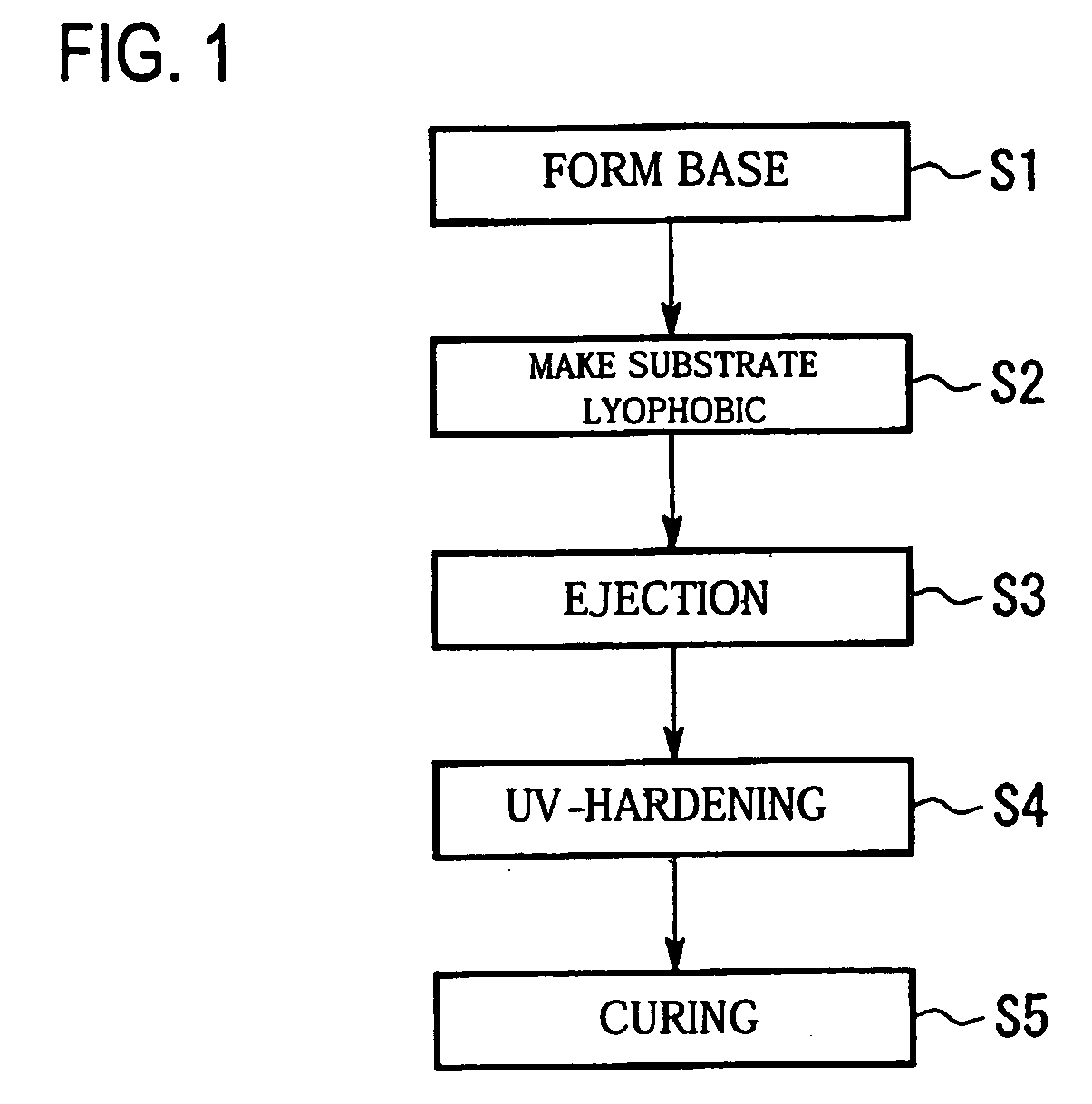
[0052]FIG. 1 is a schematic showing a process flow chart of a method of manufacturing a micro lens of the present exemplary embodiment.

[0053] First, a method of manufacturing a micro lens of the present exemplary embodiment will be described. As shown in FIG. 1, a method of manufacturing a micro lens includes a base forming process (S1) in which a base member is formed on a substrate, and a process for making the substrate lyophobic (S2) in which lyophobic treatment is implemented for an upper surface of the base member. The method also includes an ejection process (S3) in which multiple dots of a lens material are ejected on the upper surface of the lyophobicity-treated base member by a droplet ejection method so as to form micro lenses on the base member, a UV (ultraviolet rays)-hardening process (S4) in which a lens material is irradiated with UV so as to...

second exemplary embodiment

[0120] Next, a second exemplary embodiment of the present invention will now be described referring to FIGS. 9 and 10.

[0121] The method of manufacturing a micro lens of the present exemplary embodiment is substantially same as that of the first exemplary embodiment. However, the process in which a lens material is ejected is different from that of the first exemplary embodiment. Therefore, in the present exemplary embodiment, only the process of ejecting a lens material will be descried and the explanation for the base forming process and so forth will be omitted.

[0122]FIG. 9 is a schematic showing a process flow chart of a method of manufacturing a micro lens of the present exemplary embodiment.

[0123] First, the method of manufacturing a micro lens of the present exemplary embodiment will now be described. As shown in FIG. 9, a method of manufacturing a micro lens of an exemplary embodiment of the present invention includes the base forming process (S1) in which a base member is...


PUM

PropertyMeasurementUnit
Timeaaaaaaaaaa

Abstract

A method of manufacturing a micro lens that can enhance the accuracy of landing positions of droplets and can fabricate a micro lens with good shape accuracy, a micro lens, an optical device, an optical transmitting device, a laser printer, head and a laser printer are provided. In a method of manufacturing a micro lens, a given number of droplets of a lens material are ejected from a droplet ejection head on a base member formed on a substrate. The method includes stopping relative movement between the substrate and the droplet ejection head; and ejecting a plurality of the droplets on a given position on the substrate from the droplet ejection head.

Description

BACKGROUND OF THE INVENTION [0001] 1. Field of Invention [0002] Exemplary aspects of the present invention relate to a method of manufacturing a micro lens, a micro lens, an optical device, an optical transmitting device, a laser printer head, and a laser printer. [0003] 2. Description of Related Art [0004] The related art includes optical devices having a large number of minute lenses referred to as micro lenses. [0005] Examples of such optical devices include a light emitting device equipped with a laser, an optical interconnection of optical fibers, and a solid-state imaging device having a condenser lens to condense incident light. [0006] A micro lens included in such a related art optical device can be formed by a forming process using a die and photolithography. [0007] In addition, the related art includes a droplet ejection method employed for a printer and the like so as to form a micro lens, which requires a minute pattern. See Japanese Unexamined Patent Publication No. 11-...

Claims


Application Information

Patent Timeline
IPC IPC(8): B29C35/08B29D11/00G02B3/00
CPCB29D11/00365G02B3/005G02B3/0012B29D11/00B29C35/08
Inventor HASEI, HIRONORIKITO, SATOSHI
Owner SEIKO EPSON CORP
Why Eureka
Try Eureka