Method for manufacturing a droplet discharge head

Inactive Publication Date: 2012-01-05
NGK INSULATORS LTD
View PDF5 Cites 20 Cited by
  • Summary
  • Abstract
  • Description
  • Claims
  • Application Information

AI Technical Summary

Benefits of technology

[0023]According to the manufacturing method described above, the pressure chamber is formed based on forming the slurry by the mold. Therefore, even when the pressure chamber is miniaturized, or the distance between the pressure chambers adjacent to each other is short, the droplet discharge head having an excellent shape accuracy can be manufactured. In addition, the nozzle section is formed based on forming the slurry by the mold. Therefore, a surface of the nozzle section is smooth, and burrs etc. are not generated. As a result, the droplet discharge head capable of stably discharging droplets can be provided.
[0024]

Problems solved by technology

However, punching using a mold and a die forms the through hole by sheering.
As a result, a fracture surface becomes rough, or a burr and a crack may be generated.
Especially, when the pressure chamber (cavity) is miniaturized, the deformation, the burr, the crack, and the

Method used


Image

  • Method for manufacturing a droplet discharge head
  • Method for manufacturing a droplet discharge head
  • Method for manufacturing a droplet discharge head

Examples


Example

First Embodiment

[0078]First, a schematic structure will be described of a droplet discharge head 10 manufactured by a “method for manufacturing a droplet discharge head” according to a first embodiment of the present invention. Hereinafter, the manufacturing method according to the first embodiment is also referred to as a first manufacturing method.

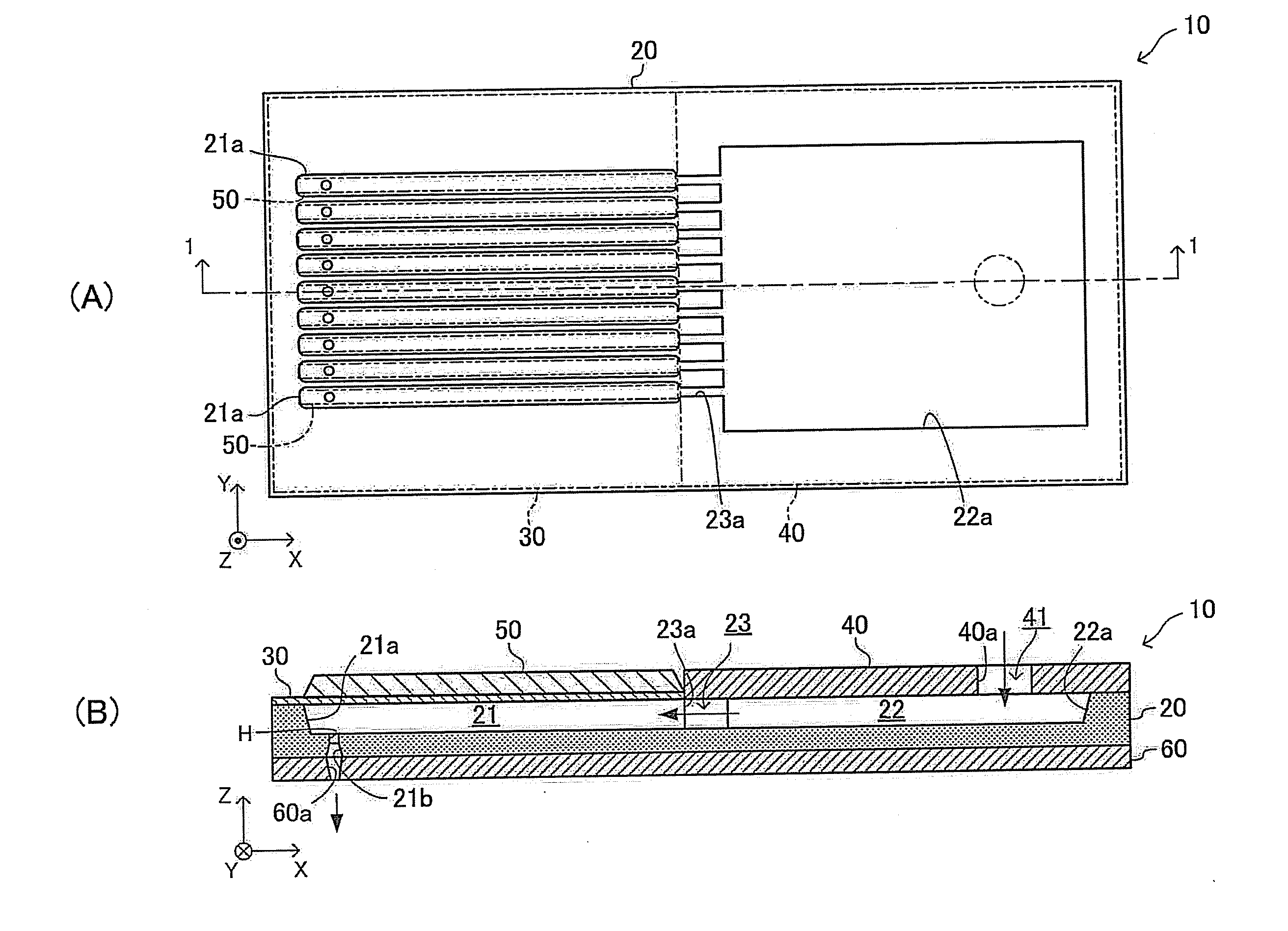
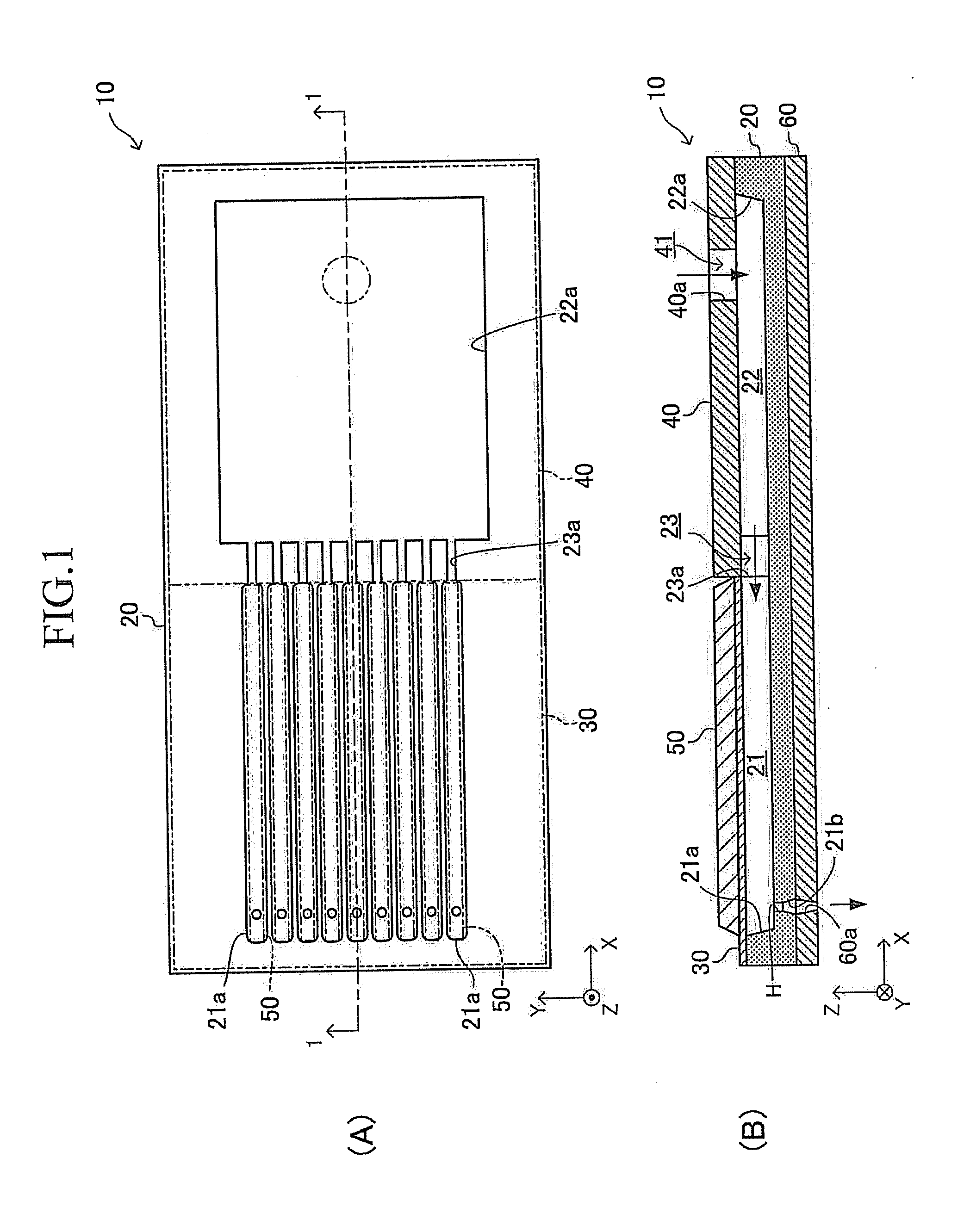
[0079]As shown in (A) and (B) of FIG. 1, the droplet discharge head 10 comprises a droplet discharge head body (head body) 20, a vibration plate 30, a liquid storage chamber cover member 40, a plurality (nine in the example shown in FIG. 1) of piezoelectric elements 50, and a discharge hole tip portion forming member 60. It should be noted that (A) of FIG. 1 is a plan view of the droplet discharge head 10 (that is, the head body 20) which is in a state in which the vibration plate 30, the liquid storage chamber cover member 40, the piezoelectric elements 50, and the discharge hole tip portion forming member 60 are removed. It should be a...

Example

Second Embodiment

[0154]Next, a “method for manufacturing a droplet discharge head” according to a second embodiment of the present invention will be described. Hereinafter, the manufacturing method according to the second embodiment is also referred to as a second manufacturing method.

[0155]The second manufacturing method is different from the first manufacturing method in that the head-body-before-fired forming step is differs from the head-body-before-fired forming step of the first manufacturing method. Hereinafter, each of steps is described sequentially.

(Slurry Preparing Step)

[0156]The slurry SL is prepared according to a step which is the same as the slurry preparing step of the first manufacturing method.

(First Mold Preparing Step)

[0157]A first mold (a pressing mold, a stamper) 100′ shown in (A) to (C) of FIG. 18 is prepared. The (A) of FIG. 18 is a cross-sectional view of the first mold 100′ cut by a plane (X-Z plane) along a longitudinal direction (the X-axis direction) of ...

Example

Third Embodiment

[0176]Next, a “method for manufacturing a droplet discharge head” according to a third embodiment of the present invention will be described. Hereinafter, the manufacturing method according to the third embodiment is also referred to as a third manufacturing method. In the third manufacturing method, only one (a single) mold is used to make a layered body-before-fired for the droplet discharge head body 20. Each of steps will be described.

(Slurry Preparing Step)

[0177]The slurry SL is prepared according to a step which is the same as the slurry preparing step of the first manufacturing method.

(Mold Preparing Step)

[0178]A mold (a pressing mold, a stamper) 300 shown in (A) to (C) of FIG. 27 is prepared. This mold is also referred to as a third mold 300. The (A) of FIG. 27 is a cross-sectional view of the third mold 300 cut by a plane (X-Z plane) along a longitudinal direction (the X-axis direction) of the third mold 300. The (B) of FIG. 27 is a cross-sectional view of t...


PUM

PropertyMeasurementUnit
Pressureaaaaaaaaaa

Abstract

In a method for manufacturing a droplet discharge head, a first mold is prepared having first convexity portions shaped like pressure chambers of the droplet discharge head. A slurry is filled into the first mold, and the first mold is placed on a first porous plate. A solvent included in the slurry permeates into the first porous plate. The slurry is dried to form a first compact. Similarly, a second mold is prepared which has second convexity portions shaped like nozzle sections of the droplet discharge head. The slurry is filled into the second mold, and the second mold is placed on a second porous plate. The solvent included in the slurry permeates into the second porous plate. The slurry is dried to form a second compact. Thereafter, the first compact and the second compact are press bonded and fired.

Description

FIELD OF THE INVENTION[0001]The present invention relates to a method for manufacturing a droplet discharge head, which discharges a droplet of, for example, a liquid containing DNA, a liquid material, a liquid fuel, and the like.BACK GROUND OF THE INVENTION[0002]Conventionally, a ceramic layered body having in its inside a hollow cavity, which is, for example, a pressure chamber for pressurizing a liquid, has been known. Such a ceramic layered body is used in a wide variety of fields including, for example, an apparatus for producing a DNA chip, an “actuator for injection a liquid” such as a fuel injection device, and the like, an actuator for an ink jet printer, a solid-oxide fuel cell (SOFC), a switching device, a sensor, and so on (refer to Patent document 1).[0003]Generally, such a ceramic layered body is manufactured according to procedures described below.[0004](1) Ceramic green sheets are prepared.[0005](2) A through hole having a predetermined shape is formed in the ceramic...

Claims


Application Information

Patent Timeline
IPC IPC(8): C04B33/32C04B37/00
CPCB41J2/1637B41J2/1607
Inventor MASE, ATSUSHITANAKA, HIDEHIKOSHIMIZU, HIDEKI
Owner NGK INSULATORS LTD
Why Eureka
Try Eureka