
Method for manufacturing structural body and manufacturing apparatus therefor

Active Publication Date: 2016-05-05
CANON KK
View PDF2 Cites 1 Cited by
  • Summary
  • Abstract
  • Description
  • Claims
  • Application Information

AI Technical Summary

Benefits of technology

The present invention provides a method and apparatus for manufacturing a structural body with high shape accuracy. This can help to address problems related to poor shape accuracy in current manufacturing processes.

Problems solved by technology

In the laminate forming method, since layer-shaped patterns are laminated to each other, for example, an object having an isolated portion, such as a front end of a hanging tree branch, in the course of manufacturing cannot be manufactured in principle.
Hence, it has been very difficult to automatically remove supports from the objects having different shapes as described above.
When the patterns are not well aligned with each other, a gap is formed therebetween, and an overhanging portion may not be supported.
In addition, when layers having a uniform thickness are formed from different materials, in view of the accuracy necessary for material supply and the change in volume caused by environmental influences, significantly tight control is required.
However, according to the method described above, if a removed material which is ground off again adheres to the object, the quality of the three-dimensional object to be manufactured may not be sufficiently satisfied in some cases.
In addition, the case in which a fine model forming portion cannot be formed to have a desired shape due to heat and / or a mechanical stress generated during grinding may occur in some cases.
Furthermore, in order to perform highly accurate grinding, a very long processing time is required.

Method used


Image

  • Method for manufacturing structural body and manufacturing apparatus therefor
  • Method for manufacturing structural body and manufacturing apparatus therefor
  • Method for manufacturing structural body and manufacturing apparatus therefor

Examples


embodiments

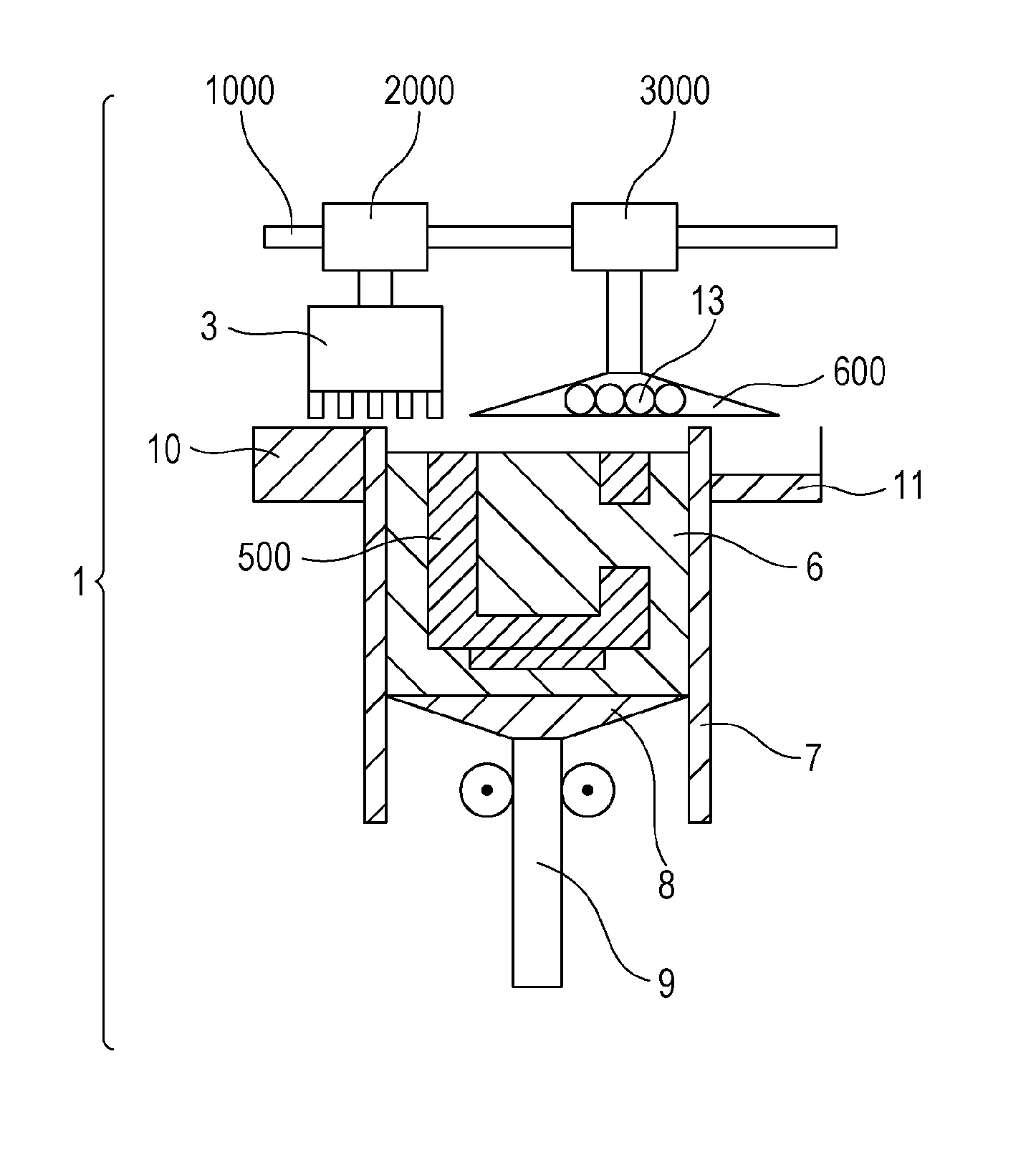
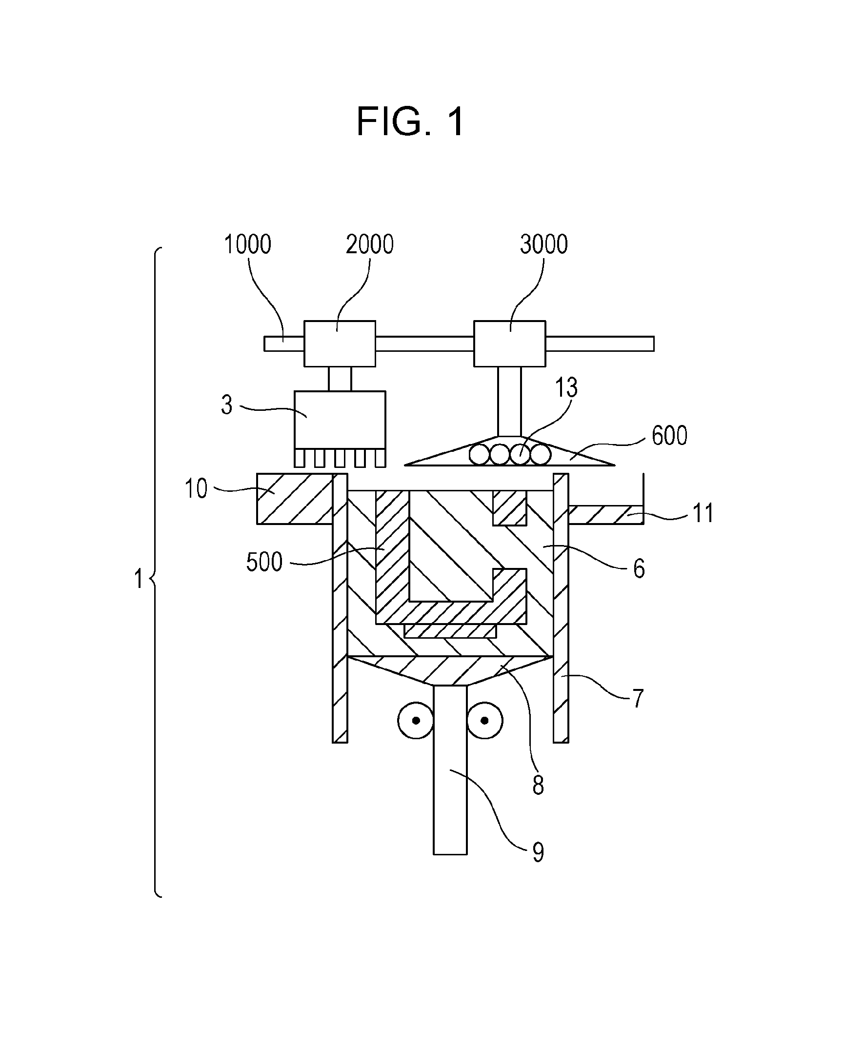
[0026]FIG. 1 is a schematic view showing one example of a laminate forming apparatus which is a manufacturing apparatus performing a method for manufacturing an object, that is, a three-dimensional structural body, according to a first embodiment of the present invention. A guide shaft 1000 of a laminate forming apparatus 1 is provided with a liquid ejection head 3 connected to a lift mechanism 2000 and a defining member 600 which accommodates UV lamps 13 therein and which is connected to a lift mechanism 3000. The height of the liquid ejection head 3 and the height of the defining member 600 can be controlled by the respective lift mechanisms. The liquid ejection head 3 can eject a liquid material which forms a structural body in a model forming container 7. On a model forming table 8, a model forming layer 500 is formed by lamination as an in-process structural body and is supported by a support member 6 which functions to support the structural body. The model forming table 8 is ...

example 1

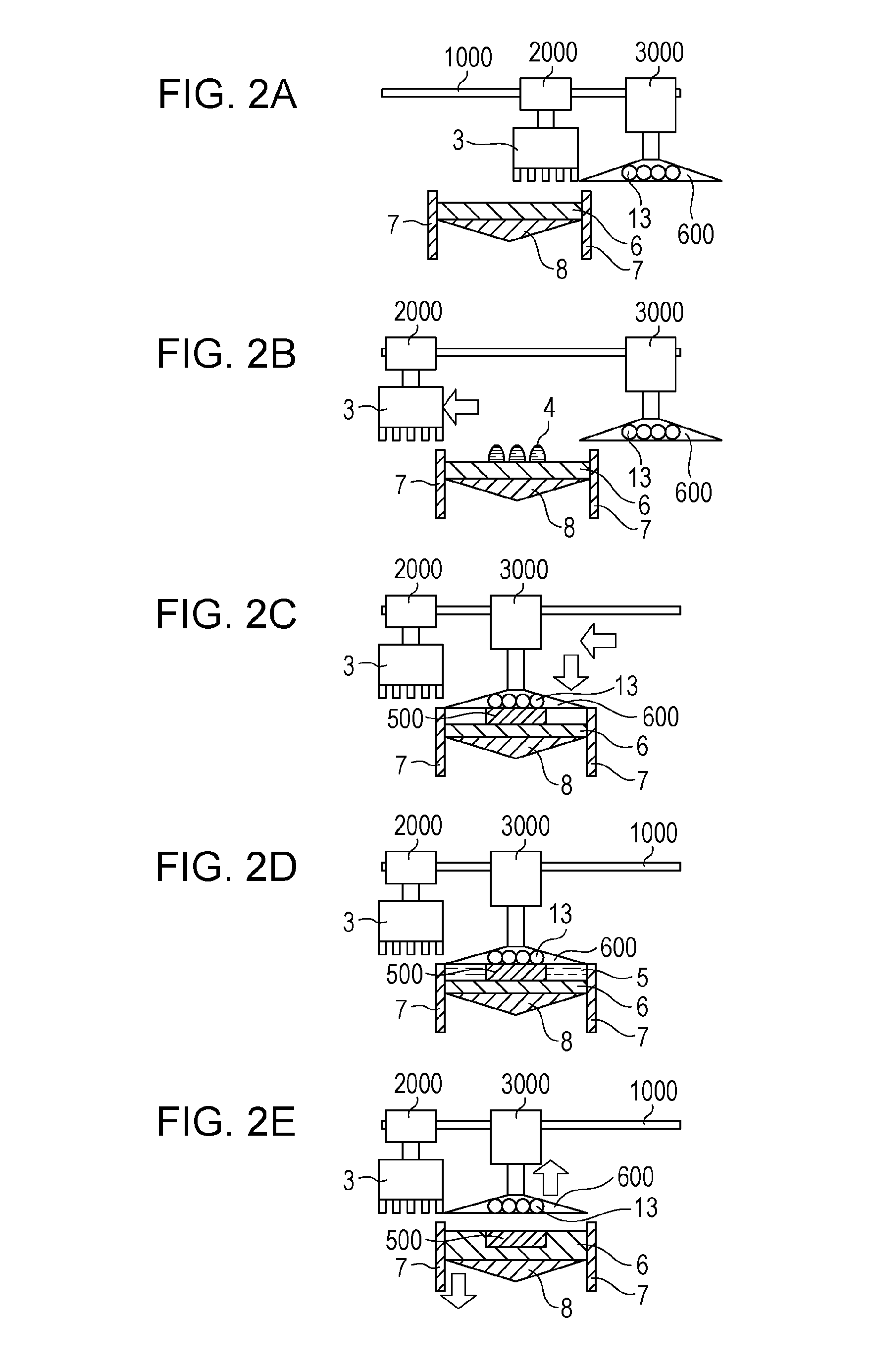
[0057]With reference to FIGS. 1 to 2E, an example of the present invention will be described.

[0058]Laminate formation is performed by using the apparatus shown in FIG. 1. The data of an object was formed in advance as a CAD data or the like and was converted into a slice data with predetermined intervals. In this example, a slice data with 25 micrometer intervals was used.

[0059]First, after a release layer was formed on the model forming table 8, the model forming table 8 was lifted up and fixed, and the defining member 600 was hold above the model forming table 8 with a gap of 25 micrometer therebetween. Next, a molten support material (paraffin wax 115 F (melting point: 47 degree Celsius); commercial product) was injected from the support filling mechanism 10, so that the support material 5 was filled into the space between model forming table 8 and the defining member 600. After the temperature was decreased to solidify the support material, the defining member 600 was lifted up,...


PUM


Abstract

In structural body formation, influence of misalignment between an in-process structural body layer and a support member layer on the shape accuracy is reduced. A method for manufacturing a structural body includes: forming a model forming layer from a liquid model forming material on an existing surface formed of at least one of prepared model forming layer and support member; while a defining surface of a defining member defining the upper surface of the model forming layer is in contact therewith; supplying a support material to fill between the existing surface and the defining surface and solidifying the support material into a support member to form a layer of the model forming layer and the support member; removing the defining member; and providing a layer of a model forming layer and a support member on the surface of the layer exposed by removal of the defining member.

Description

TECHNICAL FIELD[0001]The present invention relates to a method for manufacturing a structural body and a manufacturing apparatus therefore.BACKGROUND ART[0002]Heretofore, lamination type three-dimensional object forming methods (hereinafter referred to as “laminate forming method(s)”), such as stereolithography, have been actively used in many fields. The methods described above are each a method for forming an arbitrary three-dimensional object by sequentially laminating cross-sectional patterns thereof. In those methods, a three-dimensional object can be directly formed from a three-dimensional (design) data without using a mold or the like. Hence, those methods have been frequently used, for example, for prototype production in which a small number of three-dimensional objects are highly required to be prepared in a short period of time.[0003]As characteristic restriction of the laminate forming method, for example, an indispensable support may be mentioned. In the laminate formi...

Claims


Application Information

Patent Timeline
IPC IPC(8): B29C67/00
CPCB29C67/0092B33Y30/00B33Y10/00B29C67/0059B29C64/112B29C64/209B29C64/264B29C64/40
Inventor TANIUCHI, HIROSHINAKAJIMA, KAZUHIRO
Owner CANON KK
Learn More