
Insulator and electric connector

A technology for insulators and joints, applied to insulators, fixed/insulated contact members, etc., to solve the problems of deformation and warpage of "slender" insulators

Pending Publication Date: 2021-09-10
GUIZHOU SPACE APPLIANCE CO LTD
View PDF27 Cites 0 Cited by
  • Summary
  • Abstract
  • Description
  • Claims
  • Application Information

AI Technical Summary

Problems solved by technology

[0003] In order to solve the above technical problems, the present invention provides an insulator and an electrical connector. The insulator is composed of a plurality of base parts continuously lapped, which solves the problem of deformation and warping of the "slender" insulator

Method used


Image

  • Insulator and electric connector
  • Insulator and electric connector
  • Insulator and electric connector

Examples


Embodiment

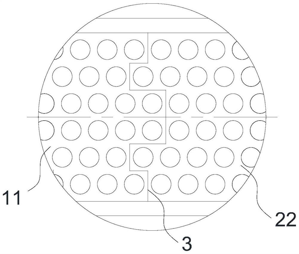
[0039] Such as Figure 1 to Figure 7 As shown, the overall length-to-width ratio of the insulator is 15:1, and the insulator is formed by lapping two parts of the first base 1 and the second base 2 in the middle. The first base 1 includes a first body 11 and an outer shell. The second base 2 includes a second body 21 and an outstretched second wing 22. The first wing 12 and the second wing 22 overlap and overlap each other along the abutting direction. And apply adhesive on all the overlapping interfaces of the first base 1 and the second base 2 to form the insulator as a whole. For an insulator with a larger aspect ratio, the number of overlapping bases can be appropriately increased to ensure the processing quality of a single base and the overall quality.

[0040] The connection between the end surface of the first protruding wing 12 and the second body 21 , and the connection between the end surface of the second protruding wing 22 and the first body 11 are provided with ...


PUM


Abstract

The invention provides an insulator and an electric connector, the insulator comprises a plurality of first bases and second bases which are continuously lapped, each first base comprises a first body and a first protruding wing extending outwards, each second base comprises a second body and a second protruding wing extending outwards, and the first protruding wings and the second protruding wings are mutually lapped and overlapped in the butt joint direction. According to the insulator and the electric connector provided by the invention, the insulator is formed by continuously lapping a plurality of base parts, so that the problems of deformation and warping of a slender insulator are solved.

Description

technical field [0001] The invention belongs to the technical field of electrical connectors, and in particular relates to an insulator and an electrical connector. Background technique [0002] At present, due to the development trend of miniaturization, the size of the electrical interface of the equipment is also reduced. On some special slender layouts, in order to save space and increase the number of effective cores, the overall "slender" interface is adopted. The upper aspect ratio even exceeds 10:1. The insulator of the electrical connector corresponding to such a special specification interface is often injection molded. Because the structure becomes slender, and the number of contact mounting holes opened on the insulator has a large impact on the plastic melt. The flow forms obstacles, especially the insulator with a large number of cores, which is extremely difficult to inject. At the same time, when the mold is demoulded, the structure is slender, and the insula...

Claims


Application Information

Patent Timeline
Patent Type & Authority Applications(China)
IPC IPC(8): H01B17/56H01R13/40
CPCH01B17/56H01R13/40
Inventor 周权龙双燕张强陈谋钦廖朝顺
Owner GUIZHOU SPACE APPLIANCE CO LTD
Learn More