Comprehensive energy box for supplying power to various devices
A technology of integrated energy and energy boxes, applied in the field of integrated energy boxes, can solve problems such as difficulty in meeting electrical equipment with different types of plugs, impact on service life and work efficiency, and inconvenient movement
- Summary
- Abstract
- Description
- Claims
- Application Information
AI Technical Summary
Problems solved by technology
Method used
Image
Examples
Embodiment 1
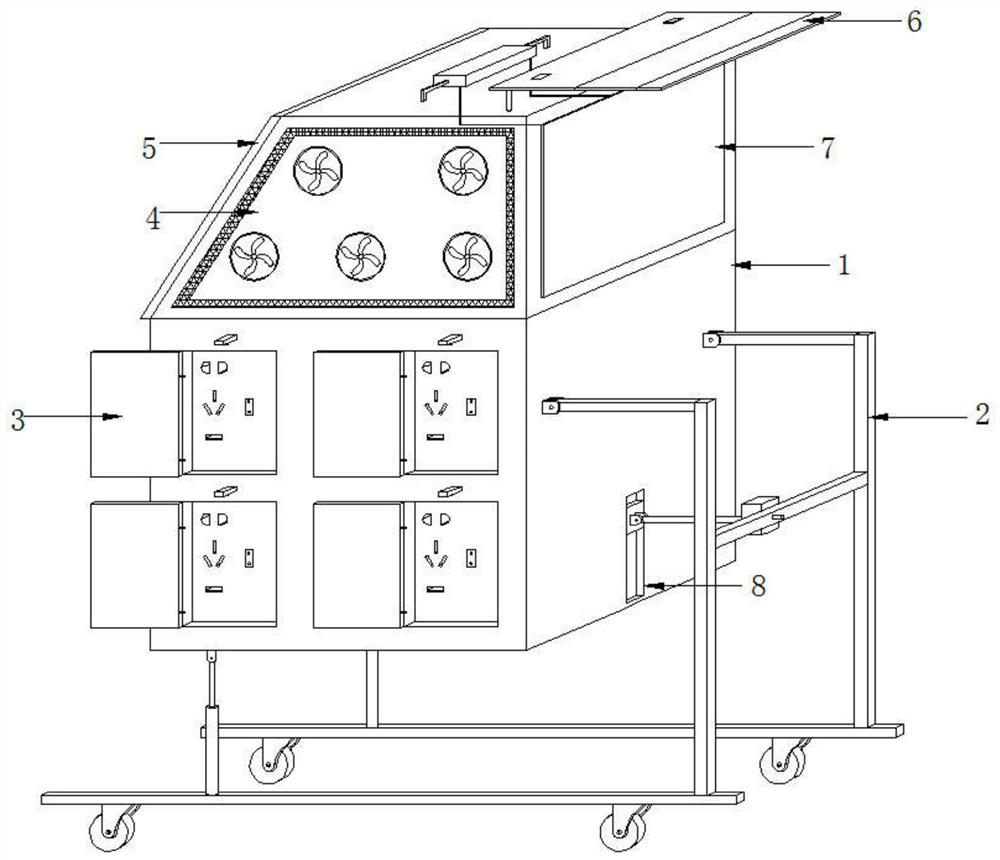
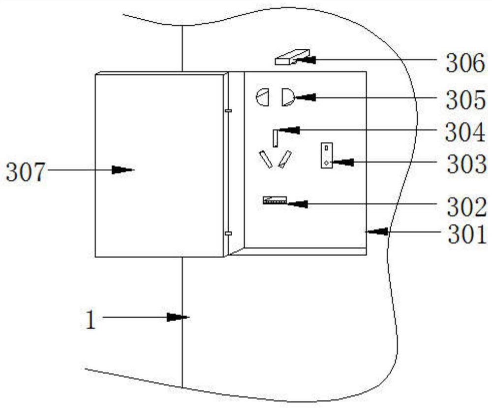
[0032] refer to figure 1 with image 3 , a comprehensive energy box for supplying power to various devices, comprising an energy box main body 1, a driving chute 8 arranged vertically at the right end of the bottom of the energy box main body 1, and the right end of the energy box main body 1 passing through the driving chute 8 A support adjustment mechanism 2 is installed, a shielding mechanism 6 and a detection and protection mechanism 7 are installed on the top of the energy box main body 1, a heat dissipation protection mechanism 4 is fixedly installed on the top front end of the energy box main body 1, and a solar photovoltaic panel 5 is fixedly installed on the top left end of the energy box main body 1 , the front end of the bottom of the energy box main body 1 is equipped with a socket mechanism 3;
[0033] The socket mechanism 3 includes an installation slot 301, four installation slots 301 are opened in the front end of the energy box main body 1 in a rectangular ar...
Embodiment 2
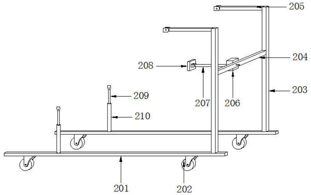
[0036] refer to figure 1 with figure 2 , a comprehensive energy box for supplying power to various devices. Compared with Embodiment 1, this embodiment also includes a support rod 203, and there are two support rods 203, and the top left ends of the two support rods 203 are fixedly installed with fixed connections. Rod 205, the left ends of the two fixed connecting rods 205 are movable hinged with the main body 1 of the energy box, a mounting plate 204 is fixedly installed between the two support rods 203, a cylinder 206 is fixedly mounted on the left end of the mounting plate 204, and the output end of the cylinder 206 is fixedly connected with Drive rod 207, the other end of drive rod 207 is movably hinged with drive slider 208, and drive slider 208 is slidably connected with drive chute 8 along the vertical direction. The lower end of the bottom plate 201 is fixedly equipped with universal wheels 202;
[0037] The upper ends of the two support base plates 201 and the posit...
Embodiment 3
[0040] refer to figure 1 with Figure 4 , a comprehensive energy box for supplying power to various devices. Compared with Embodiment 1, this embodiment further includes a cooling plate 401. The cooling plate 401 is fixedly installed on the front end of the main body 1 of the energy box. The front end of the cooling plate 401 is fixedly installed with multiple The heat dissipation fan 402, the front end of the energy box main body 1, and the positions around the heat dissipation plate 401 are all provided with a heat dissipation through hole 403, and the heat dissipation through hole 403 is provided with a heat dissipation net 404.
[0041] Working principle: through the heat dissipation through hole 403 and the start of the heat dissipation fan 402, the heat dissipation of the energy box main body 1 can be realized, and the heat dissipation mesh 404 can be installed on the heat dissipation through hole 403 to prevent dust from entering the energy box main body 1 through the h...
PUM
 Abstract
Description
Claims
Application Information
 - R&D
- Intellectual Property
- Life Sciences
- Materials
- Tech Scout
- Unparalleled Data Quality
- Higher Quality Content
- 60% Fewer Hallucinations
Browse by: Latest US Patents, China's latest patents, Technical Efficacy Thesaurus, Application Domain, Technology Topic, Popular Technical Reports.
© 2025 PatSnap. All rights reserved.Legal|Privacy policy|Modern Slavery Act Transparency Statement|Sitemap|About US| Contact US: help@patsnap.com


