Adjustable attached type scaffold anti-falling support equipment and using method
A scaffolding and attachment technology, which is applied in the field of adjustable attachment scaffolding anti-drop support equipment, can solve the problems of reduced stability, poor screw fixing effect, and poor stability of scaffolding, etc.
- Summary
- Abstract
- Description
- Claims
- Application Information
AI Technical Summary
Problems solved by technology
Method used
Image
Examples
Embodiment 1
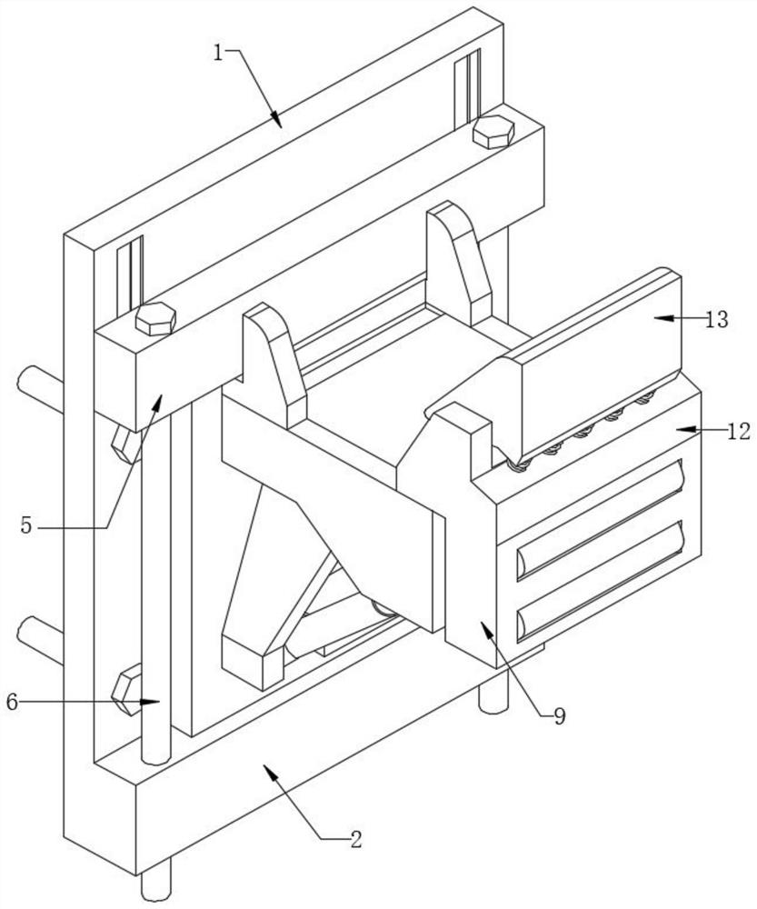
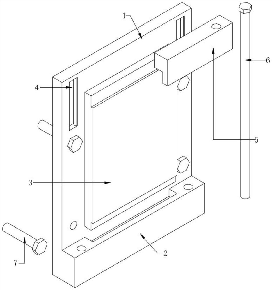
[0025] Embodiment 1: refer to Figure 1-4 , an adjustable attachment type scaffolding anti-fall support device, including a fixed frame 1, the bottom of the fixed frame 1 is provided with a base 2, and a groove is opened on the base 2, and an anchor plate is inserted into the inner wall of the groove of the base 2 3. The cross-sectional shape of the anchor plate 3 is convex, and the outer wall of one side of the fixed frame 1 is symmetrically provided with two slide grooves 4, and the inner walls of the two slide grooves 4 are slidably connected with the same lower pressure seat 5, which can be pressed down. The outer wall of the bottom of the seat 5 is provided with a groove, and two round holes are arranged symmetrically on the lower pressing seat 5 and the base 2, and the inner walls of the round holes are all plugged with the limit rod 6.
[0026] In the present invention, four circular holes are symmetrically opened on the fixed frame 1, and the inner walls of the four ci...
Embodiment 2
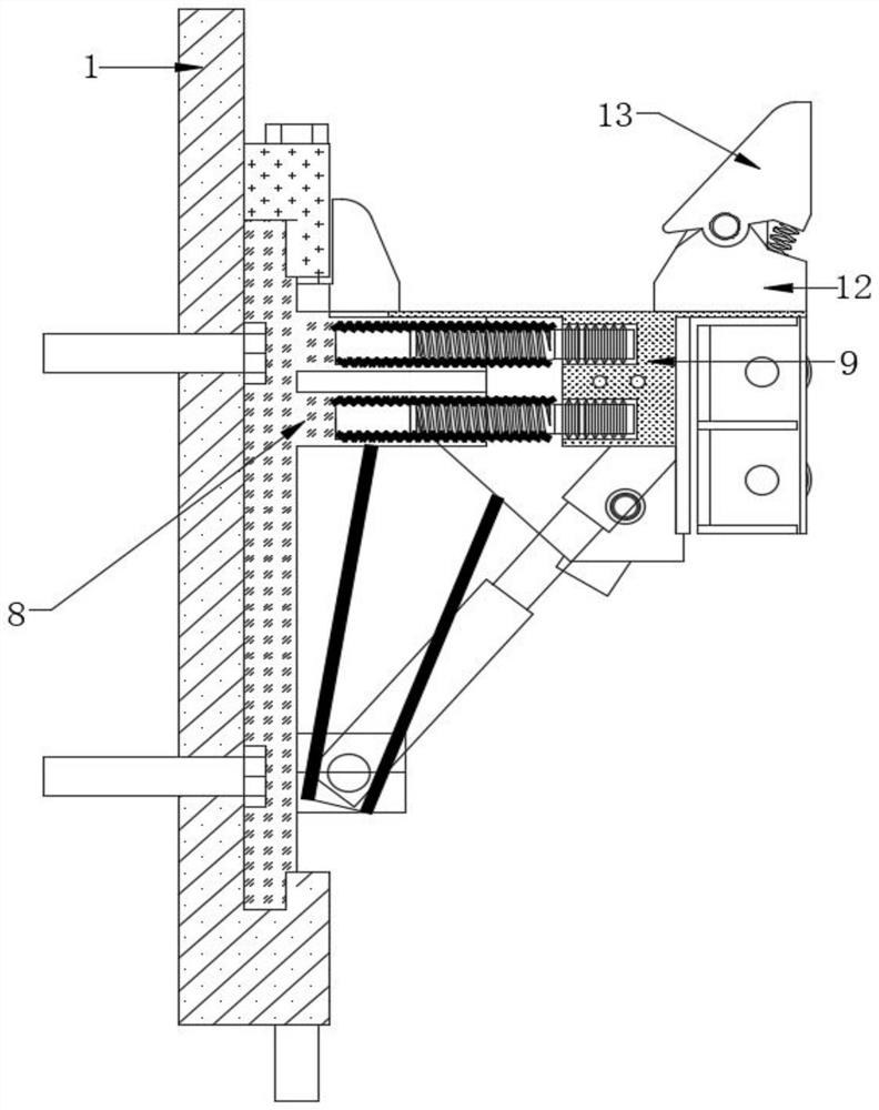
[0033] Embodiment 2: How to use Embodiment 1: Before installing the device, fix the fixing frame 1 on the concrete wall, then raise the lower pressure seat 5 and insert the anchor plate 3 into the groove of the base 2, release The lower pressure seat 5 makes it drop due to its own gravity, the lower groove of the lower pressure seat 5 is stuck on the upper end of the anchor plate 3, and the limit rod 6 is inserted into the round hole on the lower pressure seat 5 and the base 2 to complete the fixation; When a part falls off, the scaffold falls and contacts the unloading seat 13, the unloading seat 13 is deflected by force, the rotation of the rotating shaft 14 drives the elastic deformation of the coil spring 15, the unloading seat 13 presses down on the spring 16, and the unloading seat 13 is supported by the coil spring 15 and the spring The reaction force of 16 changes the falling trajectory of the scaffold, so that it falls between the fixed deck 11 and the retaining seat 1...
PUM
 Abstract
Description
Claims
Application Information
 - R&D
- Intellectual Property
- Life Sciences
- Materials
- Tech Scout
- Unparalleled Data Quality
- Higher Quality Content
- 60% Fewer Hallucinations
Browse by: Latest US Patents, China's latest patents, Technical Efficacy Thesaurus, Application Domain, Technology Topic, Popular Technical Reports.
© 2025 PatSnap. All rights reserved.Legal|Privacy policy|Modern Slavery Act Transparency Statement|Sitemap|About US| Contact US: help@patsnap.com


