Anesthetic laryngoscope

An anesthesia laryngoscope and laryngoscope technology, applied in the laryngoscope field, can solve problems such as easy fogging of the camera, inability to adjust the angle of ordinary laryngoscopes, and discomfort of the trachea with metal lenses, so as to facilitate observation, avoid virus alternation, and facilitate fixation The effect of disassembly

Pending Publication Date: 2020-02-21
李庆忠
View PDF4 Cites 3 Cited by
  • Summary
  • Abstract
  • Description
  • Claims
  • Application Information

AI Technical Summary

Problems solved by technology

[0003] The object of the present invention is to provide an anesthesia laryngoscope to solve the above-mentioned problems of ordinary laryngoscopes in the background art that the angle cannot be adjusted, the camera is easy to fog, and the metal lens is directly in contact with the trachea.

Method used


Image

  • Anesthetic laryngoscope
  • Anesthetic laryngoscope
  • Anesthetic laryngoscope

Examples


Embodiment 1

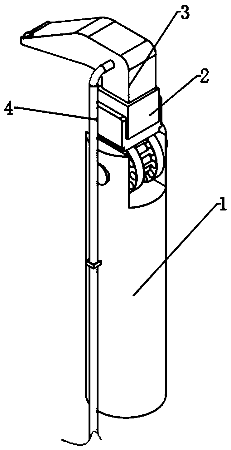
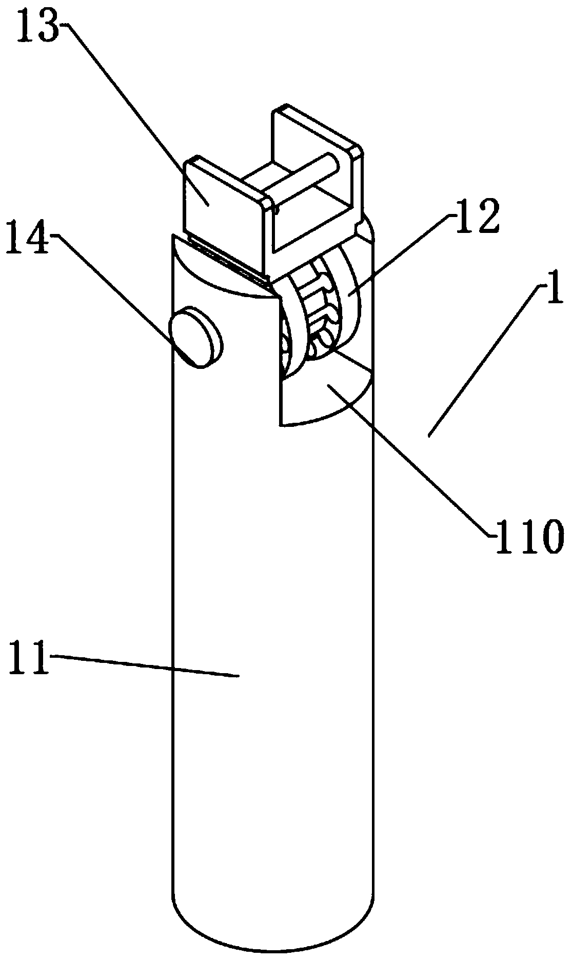
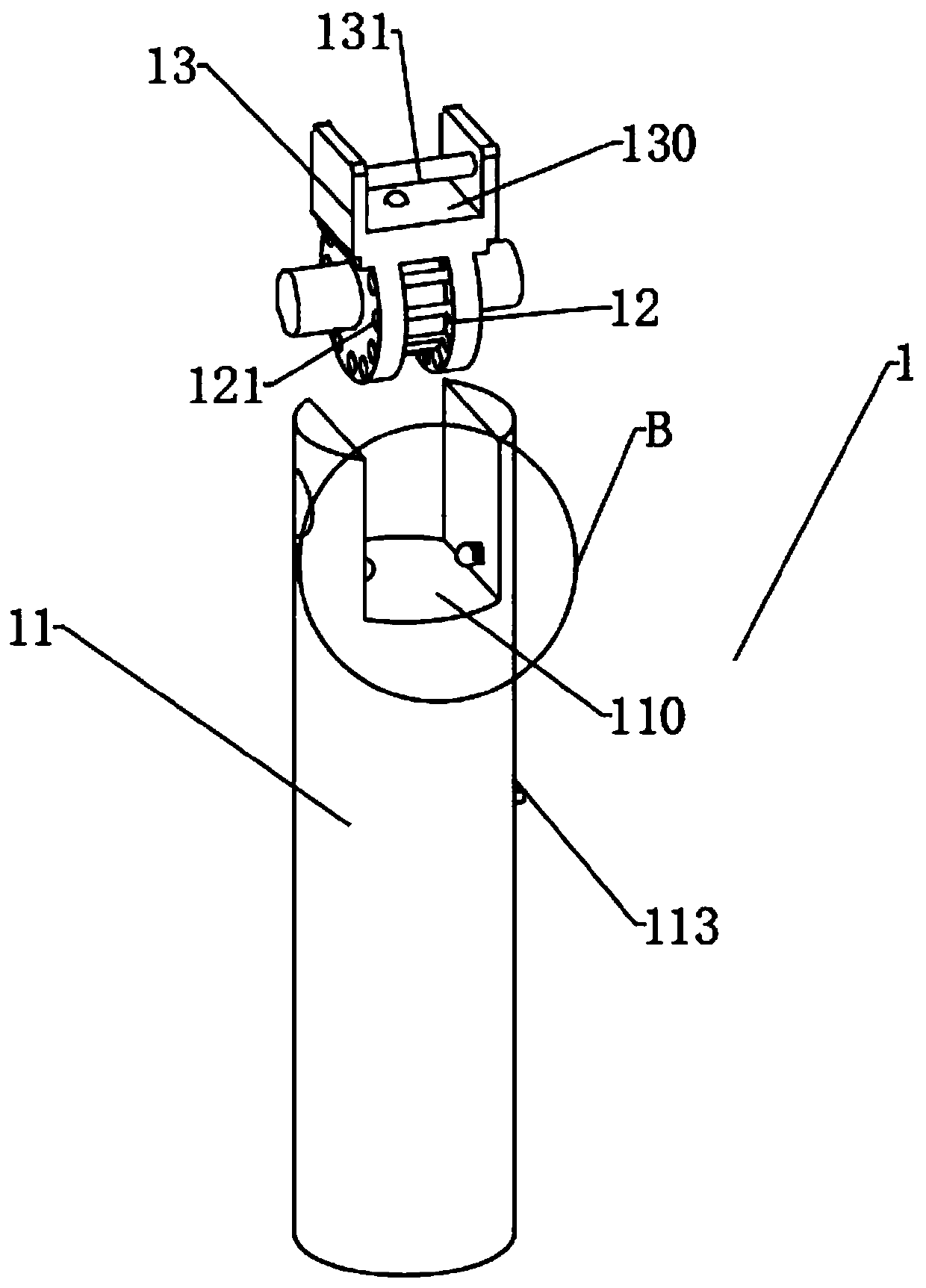
[0029] A kind of anesthesia laryngoscope, in order to solve the common laryngoscope in the above-mentioned background technology that the angle cannot be adjusted, the camera is easy to fog and the metal mirror directly contacts the trachea discomfort problem, as a preferred embodiment, as figure 1 , figure 2 , image 3 , Figure 4 , Figure 5 , Figure 6 , Figure 7 and Figure 8 As shown, it includes the debugging handle 1 and the top of the debugging handle 1 is clamped with the laryngoscope device 2. The debugging handle 1 includes a handle 11. The top of the handle 11 is provided with a handle groove 110. The inner cavity of the handle groove 110 is rotated by a rotating shaft 14. A rotating disk 12. The top of the rotating disk 12 is fixedly connected to the lower joint 13, and the top of the lower joint 13 is provided with a limiting groove 130, and the inner cavity of the limiting groove 130 is fixedly connected to the clamping shaft 131. The laryngoscope device ...


PUM


Abstract

The invention relates to the technical field of laryngoscopes, in particular to an anaesthetic laryngoscope. The anaesthetic laryngoscope comprises a debugging handle and a laryngoscope device clampedat the top of the debugging handle, the debugging handle comprises a handle, a handle groove is formed in the top of the handle, a rotating disc is rotationally arranged in an inner cavity of the handle groove through a rotating shaft, the top of the rotating disc is fixedly connected to a lower connector, a limiting groove is formed in the top of the lower connector, an inner cavity of the limiting groove is fixedly connected to a clamping shaft, the laryngoscope device comprises an upper connector, a clamping shaft groove is formed in the side face of the upper connector, the clamping shaftgroove is matched with the clamping shaft, the top of the upper connector is fixedly connected to a laryngoscope lens, a camera is arranged on the laryngoscope lens, the outer side of the laryngoscope lens is sleeved with a transparent soft sleeve, the transparent soft sleeve is clamped to the top of the upper connector, and an inner cavity of the transparent soft sleeve penetrates through a suction pipe. The angle between the laryngoscope lens and the handle can be adjusted to facilitate observation, and the transparent soft sleeve can prevent the camera from fogging and prevent the metal laryngoscope lens from contacting with the trachea to cause discomfort.

Description

technical field [0001] The invention relates to the technical field of laryngoscopes, in particular to an anesthesia laryngoscope. Background technique [0002] Due to the deep position of the larynx and its complex physiological structure, it cannot be directly observed. Some special inspection methods are needed for laryngeal examination, such as indirect laryngoscope, direct laryngoscope, fiber laryngoscope, electronic laryngoscope, strobe laryngoscope, Ultra-high-speed cinematography, sonogram or glottogram, the lens and handle angle of the current anesthesia laryngoscope is fixed, and the physiological characteristics of patients are different. When the patient has small mouth, small jaw, high glottis, epiglottis hypertrophy or neck disease It is not advisable to lean back too much, which makes it difficult to directly observe the glottis. At this time, there are different degrees of difficulty in intubation, and because the human body is humid and has a certain tempera...

Claims


Application Information

Patent Timeline
Patent Type & Authority Applications(China)
IPC IPC(8): A61B1/267A61B1/04A61B1/00A61M1/00
CPCA61M1/0023A61B1/00064A61B1/00131A61B1/04A61B1/267
Inventor 李庆忠
Owner 李庆忠
Why Eureka
Try Eureka