Device for cleaning floccules in textile printing and dyeing wastewater

A cleaning device and textile technology, which is applied in textile industry wastewater treatment, grease/oily substance/floating matter removal device, water/sewage treatment, etc., can solve the problems of inconvenient cleaning, waste of resources, inconvenient centralized treatment, etc., and achieve convenient Fixed disassembly, reduced consumption, and reduced difficulty effects

Inactive Publication Date: 2018-11-06
嘉兴星创科技有限公司
View PDF6 Cites 3 Cited by
  • Summary
  • Abstract
  • Description
  • Claims
  • Application Information

AI Technical Summary

Problems solved by technology

[0002] Textile wastewater is mainly wastewater containing natural impurities, fat, starch and other organic matter produced during raw material cooking, rinsing, bleaching, and sizing. Printing and dyeing wastewater is produced in multiple processes such as washing, printing, and sizing. Organic matter such as starch, cellulose, lignin, and detergent, as well as inorganic matter such as alkali, sulfide, and various salts, are highly polluting. After preliminary filtration of wastewater, the residual flocs in the wastewater need to be cleaned. Existing The best treatment method is to add a coagulant to make the floc coagulate and precipitate, but this method takes a lot of time to settle the floc, and also needs to inject a large amount of coagulant, resulting in waste of resources, and the floc cannot be completely precipitated during the coagulation process. At the same time, the precipitated flocs are not easy to clean. After a long period of sedimentation, they will accumulate at the bottom of the sedimentation tank, which is not easy to clean up or centralized treatment.

Method used


Image

  • Device for cleaning floccules in textile printing and dyeing wastewater
  • Device for cleaning floccules in textile printing and dyeing wastewater
  • Device for cleaning floccules in textile printing and dyeing wastewater

Examples


Embodiment Construction

[0019] The following will clearly and completely describe the technical solutions in the embodiments of the present invention with reference to the accompanying drawings in the embodiments of the present invention. Obviously, the described embodiments are only some, not all, embodiments of the present invention. Based on the embodiments of the present invention, all other embodiments obtained by persons of ordinary skill in the art without making creative efforts belong to the protection scope of the present invention.

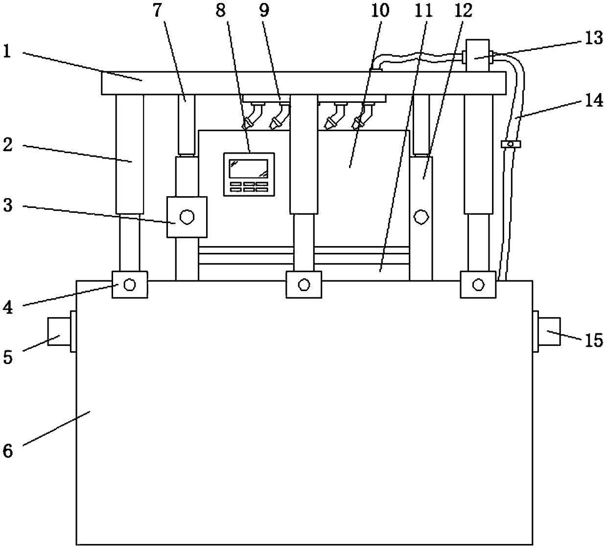
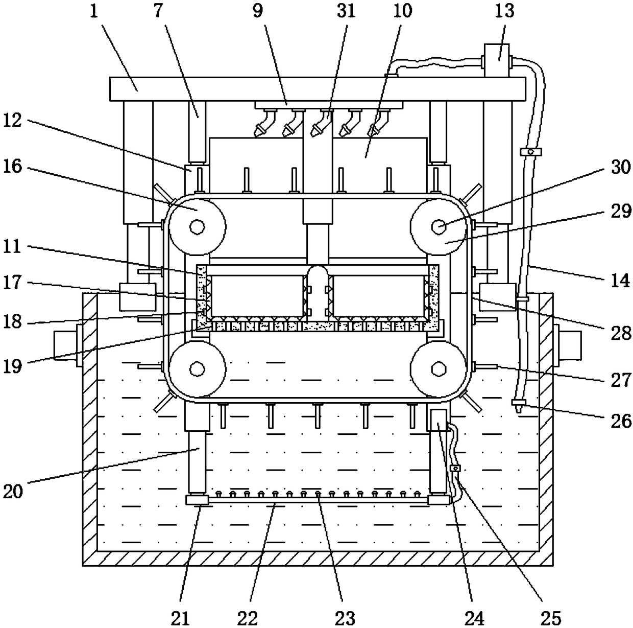
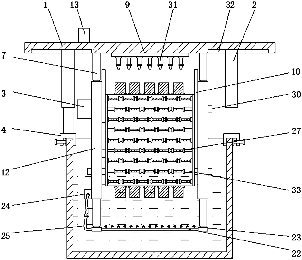
[0020] see Figure 1-5 , an embodiment provided by the present invention: a cleaning device for flocs in textile printing and dyeing wastewater, comprising a fixed plate 1, a pool body 6, a collection box 11 and a transmission chain 28, and the two ends of the pool body 6 are respectively installed There are water inlet pipe 5 and water outlet pipe 15, both sides of pool body 6 tops are all evenly installed with fixing seat 4, and the center of fixing seat 4 i...


PUM


Abstract

The invention discloses a device for cleaning floccules in textile printing and dyeing wastewater. The device comprises a fixing plate, a pool, a collection box and a transmission chain, wherein fixing seats are uniformly mounted on two sides of the top of the pool; the fixing plate is arranged at the tops of the fixing seats; fixing rods are mounted at the bottom of the fixing plate through second electric telescopic rods; a motor is mounted on one fixing rod; an output shaft of the motor penetrates the two fixing rods at the same end and is equipped with driving wheels; driven wheels are mounted on rotating shafts mounted between the fixing rods at one ends of the driving wheels; the driven wheels and the driving wheels are fixedly connected through the transmission chain. By mounting the fixing plate, the pool, the collection box and the transmission chain, a pipe network is fixed between mounting seats at the bottom ends of third electric telescopic rods mounted at the bottom endsof the fixing rods, aerators are uniformly mounted on the pipe network, and the floccules in the wastewater are jacked up by airflow conveniently through aeration of the aerators and float on the upper layer of the wastewater, thereby being convenient to clean.

Description

technical field [0001] The invention relates to the technical field of industrial wastewater cleaning, in particular to a device for cleaning flocs in textile printing and dyeing wastewater. Background technique [0002] Textile wastewater is mainly wastewater containing natural impurities, fat, starch and other organic matter produced during raw material cooking, rinsing, bleaching, and sizing. Printing and dyeing wastewater is produced in multiple processes such as washing, printing, and sizing. Organic matter such as starch, cellulose, lignin, and detergent, as well as inorganic matter such as alkali, sulfide, and various salts, are highly polluting. After preliminary filtration of wastewater, the residual flocs in the wastewater need to be cleaned. Existing The best treatment method is to add a coagulant to make the floc coagulate and precipitate, but this method takes a lot of time to settle the floc, and also needs to inject a large amount of coagulant, resulting in wa...

Claims


Application Information

Patent Timeline
Patent Type & Authority Applications(China)
IPC IPC(8): C02F1/20C02F1/52C02F1/40C02F103/30
CPCC02F1/20C02F1/40C02F1/5281C02F2103/30
Inventor 曹才振吴超张明孙笛孙迪陆东杰
Owner 嘉兴星创科技有限公司
Why Eureka
Try Eureka