A test device for buzzer production

A test device and buzzer technology, which is applied to measurement devices, instruments, alarms, etc., can solve the problem that the use performance of the buzzer test equipment cannot meet the needs of use, and achieve the effect of ensuring accuracy

Active Publication Date: 2021-11-02
常州尊铮机械设备有限公司
View PDF9 Cites 0 Cited by
  • Summary
  • Abstract
  • Description
  • Claims
  • Application Information

AI Technical Summary

Problems solved by technology

[0005] In view of the above situation, in order to overcome the defects of the prior art, the present invention provides a test device for buzzer production, which effectively solves the problem that the performance of the existing buzzer test equipment cannot meet the use requirements

Method used


Image

  • A test device for buzzer production
  • A test device for buzzer production
  • A test device for buzzer production

Examples


Embodiment 1

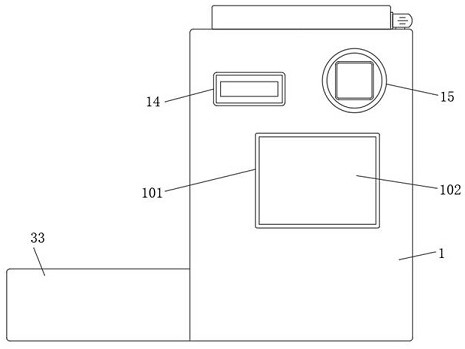
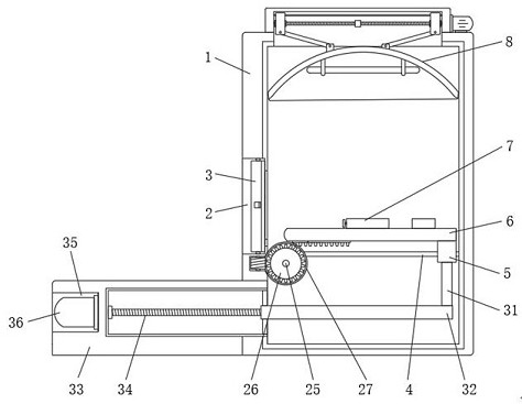
[0054] Depend on Figure 1 to Figure 9 Given, the present invention comprises test box body 1, and the middle part of one end of test box body 1 is provided with placement opening 2, and the inner rotation of placement opening 2 is installed with airtight door 3, through the setting of airtight door 3, can effectively place mouth 2 Sealing is carried out, so that high temperature leakage can be effectively avoided. Both sides of the lower part of the inner cavity of the test box 1 are equipped with slide bars 4, and a moving block 5 is slidably installed between the surfaces of the two slide bars 4. The top of the moving block 5 The placement board 6 is fixedly installed. Through the setting of the slide bar 4 and the moving block 5, the placement board 6 can be moved effectively so that the buzzer can be put into the inside of the test box 1 for detection. The top of the placement board 6 A buzzer clamping assembly 7 is installed in the middle, a heater 8 is installed on the ...

Embodiment 2

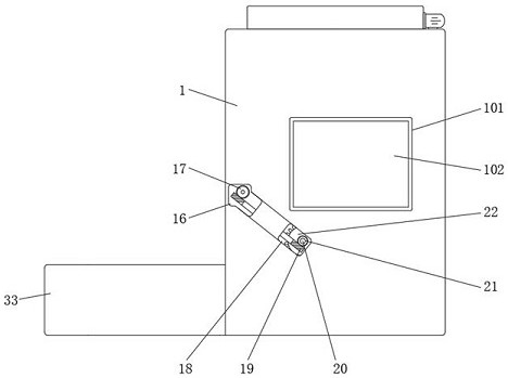
[0079] On the basis of embodiment one, by Figure 1 to Figure 8 Given, the inside of the square groove 9 is provided with an inner groove 16, one end of the threaded pin 10 extends to the inside of the inner groove 16 and is fixedly installed with a first turbine 17, and the lower part of one side of the inner cavity of the test box body 1 is provided with a groove 18 , a first worm 19 is rotatably installed between the inner groove 16 and the groove 18, and one end of the first worm 19 is engaged with the first worm gear 17;

[0080] The inside of the groove 18 is rotatably equipped with a first rotating pin 20, and the first rotating pin 20 is fixedly installed with a second worm wheel 21 on one side inside the groove 18, and the second worm wheel 21 is meshed with the other end of the first worm 19. And one end of the first rotating pin 20 is fixedly equipped with a first gear 22, and one side of the bottom of the placement plate 6 is fixedly equipped with a short rack 23, ...

Embodiment 3

[0090] Embodiment three, on the basis of embodiment one, by Figure 6 Given, the buzzer clamping assembly 7 includes a fixed ring 701, the fixed ring 701 is fixedly installed on the top of the placement plate 6, and the surface of the fixed ring 701 is movably inserted with a T-shaped bar 702, one end of the T-shaped bar 702 is located at The inside of the fixed ring 701 is fixedly connected with an arc-shaped card 703, and one side of the T-shaped bar 702 is sleeved with a spring 704. Effectively install and fix the buzzer to ensure the stability of the buzzer during the detection process;

[0091] The process of installing the buzzer: First, snap the bottom of the buzzer between the inner arc surface of the fixed ring 701 and the inner arc surface of the arc card 703, and use the elastic force of the spring 704 to make the buzzer firmly installed on the Between the fixed ring 701 and the arc-shaped card 703, the buzzer can be kept effectively and stable during the detection p...


PUM


Abstract

The invention relates to the technical field of test devices, and discloses a test device for buzzer production, which solves the problem that the performance of existing buzzer test equipment cannot meet the use requirements. It includes a test box, the There is a placement opening in the middle of one end of the test box, and a sealed door is installed on the inside of the placement opening. Slide bars are installed on both sides of the lower part of the test box inner cavity, and a moving block is installed between the surfaces of the two slide bars. The top of the block is fixed with a placement plate, the middle part of the top of the placement plate is installed with a buzzer clamping assembly, and the top of the test box is equipped with a heater; the test device produced by this buzzer has good sealing performance, At the same time, decibel detection can be carried out in the process of high temperature detection, thus effectively ensuring the accuracy of high temperature detection and decibel detection data, and avoiding the influence of high temperature and high sound on the detection personnel during the detection process.

Description

technical field [0001] The invention belongs to the technical field of testing devices, in particular to a testing device for buzzer production. Background technique [0002] The buzzer is an electronic sounder with an integrated structure. It is powered by DC voltage and is widely used as a sounding device in electronic products such as computers, printers, copiers, alarms, electronic toys, automotive electronic equipment, telephones, and timers. The buzzer is mainly divided into two types: piezoelectric buzzer and electromagnetic buzzer; the buzzer uses the letter "H" or "HA" in the circuit. [0003] The patent application with notification number CN210513406U discloses a high-temperature sound wave testing device for the production of electromagnetic buzzers, which is heated by heating equipment, and the heat is transported to the inside of the main box by means of a through pipe, a connecting pipe and an air intake pipe, so that the The top and bottom of the buzzer are ...

Claims


Application Information

Patent Timeline
Patent Type & Authority Patents(China)
IPC IPC(8): G01H17/00G01K13/00G08B29/00G10K9/00C03C25/48C03C25/6226
CPCG01H17/00G01K13/00G10K9/00G08B29/00C03C25/48C03C25/6226
Inventor 顾旭亚徐立东
Owner 常州尊铮机械设备有限公司
Why Eureka
Try Eureka