Drift diagnosis method and device of sensor, electronic equipment and storage medium

A diagnostic method and technology of a diagnostic device, applied in the fields of instrumentation, design optimization/simulation, special data processing applications, etc., can solve problems such as limited use

Active Publication Date: 2021-09-14
GD MIDEA HEATING & VENTILATING EQUIP CO LTD +1
View PDF6 Cites 0 Cited by
  • Summary
  • Abstract
  • Description
  • Claims
  • Application Information

AI Technical Summary

Problems solved by technology

[0004] The purpose of the embodiments of the present application is to provide a sensor drift diagnosis method, device, electronic equipment, and storage medium, and to provide a general judgment method for sensor and component characteristic parameter drift, so as to solve the problem that the existing methods cannot use general methods for judgment The problem of limited use caused by

Method used


Image

  • Drift diagnosis method and device of sensor, electronic equipment and storage medium
  • Drift diagnosis method and device of sensor, electronic equipment and storage medium
  • Drift diagnosis method and device of sensor, electronic equipment and storage medium

Examples


Embodiment 1

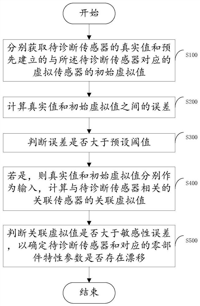
[0070] Please see figure 1 , figure 1 It is a flow chart of a sensor drift diagnosis method provided by the embodiment of the present application. This method calculates the virtual value of the sensor and performs a series of judgments to obtain a general judgment method for the drift of the characteristics of the sensor and parts, which specifically includes the following steps:

[0071] Step S100: Obtain the actual value of the sensor to be diagnosed and the initial virtual value of the pre-established virtual sensor corresponding to the sensor to be diagnosed respectively;

[0072] Establish a virtual sensor calculation model corresponding to the sensors in the system. The virtual sensor uses one or more real sensor values ​​in the system and the characteristic parameters of one or more components as input, and outputs the virtual sensor calculation model through a virtual sensor calculation model. The initial dummy value for the virtual sensor. By analogy, other sensor...

Embodiment 2

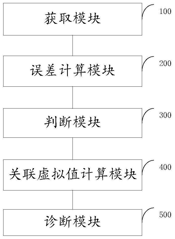
[0159] An embodiment of the present application provides a sensor drift diagnosis device, such as image 3 As shown, it is a structural block diagram of the drift diagnosis device of the sensor, and the device includes:

[0160] An acquisition module 100, configured to respectively acquire the actual value of the sensor to be diagnosed and the pre-established initial virtual value of the corresponding virtual sensor;

[0161] An error calculation module 200, configured to calculate the error between the real value and the initial virtual value;

[0162] A judging module 300, configured to judge whether the error is greater than a preset threshold;

[0163] The associated virtual value calculation module 400 is used to calculate the associated virtual value of the associated sensor related to the sensor to be diagnosed, if it is greater than the preset threshold, the real value and the initial virtual value are respectively used as input;

[0164] Diagnosis module 500, config...


PUM


Abstract

The embodiment of the invention provides a drift diagnosis method and device of a sensor, electronic equipment and a storage medium, and relates to the technical field of air conditioners. The method comprises the following steps: respectively acquiring a true value of a to-be-diagnosed sensor and a pre-established initial virtual value of a virtual sensor corresponding to the to-be-diagnosed sensor; calculating an error between the true value and the initial virtual value; judging whether the error is greater than a preset threshold value or not; if yes, taking the true value and the initial virtual value as input, and calculating an associated virtual value of an associated sensor related to the to-be-diagnosed sensor; and judging whether the associated virtual value is greater than a sensitivity error or not so as to determine whether the sensor to be diagnosed and the characteristic parameters of the corresponding part drift or not, and providing a general judgment method for the drift of the characteristic parameters of the sensor and the part. Therefore, the problem that use is limited due to the fact that a general method cannot be used for judgment in an existing method is solved.

Description

technical field [0001] The present application relates to the technical field of air conditioning, in particular, to a sensor drift diagnosis method, device, electronic equipment and storage medium. Background technique [0002] Due to the aging of the sensor and the influence of the installation environment, the phenomenon of sensor drift generally exists in engineering systems. The current sensor drift judgment method is mainly judged by the relationship between two sensors under special working conditions, which leads to different judgment methods for different sensors, which obviously has great limitations. [0003] In addition, the virtual sensor values ​​obtained through physical modeling often require that the characteristic parameters of related parts be relatively accurate, but due to individual differences in parts or the attenuation of parts during operation, there is a large difference between the characteristic parameters and the initial modeling values. discre...

Claims


Application Information

Patent Timeline
Patent Type & Authority Applications(China)
IPC IPC(8): G06F30/20G01D18/00
CPCG06F30/20G01D18/00
Inventor 郑春元丁云霄郭芳程
Owner GD MIDEA HEATING & VENTILATING EQUIP CO LTD
Why Eureka
Try Eureka