Winding core and coil component

A wire winding and core technology, which is applied to transformer/inductor components, transformer/inductor coils/windings/connections, electrical components, etc., and can solve problems such as the deviation of the shape of the winding core 5

Pending Publication Date: 2021-09-14
MURATA MFG CO LTD
View PDF1 Cites 0 Cited by
  • Summary
  • Abstract
  • Description
  • Claims
  • Application Information

AI Technical Summary

Problems solved by technology

[0013] Unintended deformations in the flange portions 3, 4 as described above not only lead to deviations in the outer shape of the winding core 5, but also have undesired effects on the physical and electrical characteristics of the winding core 5.

Method used


Image

  • Winding core and coil component
  • Winding core and coil component
  • Winding core and coil component

Examples


Embodiment Construction

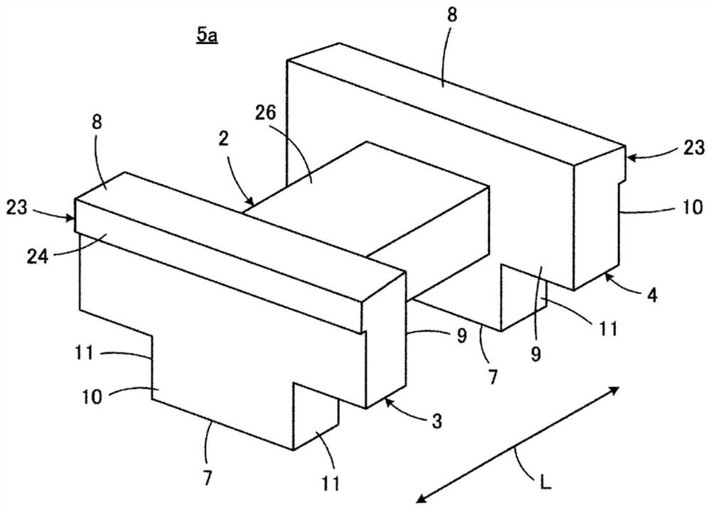
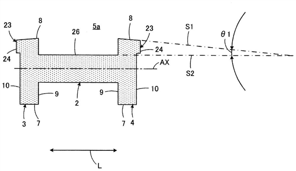
[0030] As mentioned above, Figure 5 It is a figure which shows the coil component 1 described in patent document 1, and in Figure 5 In the coil component 1 shown, the winding core 5 is replaced by figure 1 The shown member of the winding core 5a is a coil member according to one embodiment of the present invention. Thus, in figure 1 and figure 2 on the basis of the Figure 5 Next, the winding core 5a according to the first embodiment of the present invention and the coil component provided therewith will be described. In addition, in the following description, for the Figure 5 elements equivalent to those shown, use the same Figure 5 The reference numbers shown have the same reference numbers.

[0031] In the first embodiment of the present invention, the coil component also constitutes, for example, a common mode choke coil, and also includes the winding core 5a. The winding core 5a has: a winding core portion 2 extending along the longitudinal direction L; 1st end...


PUM


Abstract

The invention provides a winding core that can have an effect of preventing undesired deformation which is made of ceramics and has a convex step portion on the top surface side of the outer end surface of a flange portion. The winding core includes: a winding core portion extending in a length direction; first and second flange portions respectively provided at first and second end portions of the winding core portion in the length direction, and each having a bottom surface, a top surface on a side opposite to the bottom surface, an inner end surface facing the winding core portion side, and an outer end surface on a side opposite to the inner end surface, with a convex step portion on the top surface side of the outer end surface. The winding core portion has an upper surface facing substantially the same direction as a direction in which the top surface faces. When viewed on a virtual plane in which a central axis of the winding core portion is located and which extends in a direction orthogonal to the bottom surface, a first straight line passing through the top surface and a second straight line passing through the upper surface intersect outside the outer end surface at an angle of from 0.3 degrees to 5 degrees.

Description

technical field [0001] The present invention relates to a winding core for winding a wire around a coil component and a coil component including the same, and particularly relates to an aspect of the winding core made of ceramics. Background technique [0002] The technology concerned by the present invention is described in, for example, Japanese Patent Application Laid-Open No. 2018-148080 (Patent Document 1). exist Figure 5 In , the coil component 1 described in Patent Document 1 is shown. [0003] refer to Figure 5 The coil component 1 is, for example, a component constituting a common mode choke coil, and includes a winding core 5 . The winding core 5 has: a winding core portion 2 extending along the longitudinal direction L; 1st end, 2nd end. The coil component 1 may further include a top plate 6 spanning between the first flange portion 3 and the second flange portion 4 . [0004] exist Figure 6 , only shown separately Figure 5 The winding core 5 in the shown...

Claims


Application Information

Patent Timeline
Patent Type & Authority Applications(China)
IPC IPC(8): H01F27/24H01F27/26
CPCH01F27/24H01F27/26H01F17/045H01F3/08H01F27/2823H01F27/306H01F27/29H01F41/0246
Inventor 桥本贤治
Owner MURATA MFG CO LTD
Why Eureka
Try Eureka