Communication Radar Signal Transceiver Method Based on Continuous Phase Modulation and Chirp

A linear frequency modulation and phase modulation technology, which is applied in pilot signal distribution, radio wave reflection/reradiation, phase modulation carrier system, etc., can solve the problem of low spectrum utilization efficiency, single communication signal transmission function or radar target detection function, etc. problem, to achieve the effect of improving spectrum utilization efficiency

Active Publication Date: 2022-08-02
HARBIN INST OF TECH
View PDF1 Cites 0 Cited by
  • Summary
  • Abstract
  • Description
  • Claims
  • Application Information

AI Technical Summary

Problems solved by technology

[0003] The purpose of the present invention is to solve the problem that the existing communication radar integrated system can only realize the communication signal transmission function or the radar target detection function alone, resulting in low frequency spectrum utilization efficiency, and now provides a communication radar signal based on phase modulation and linear modulation send and receive method

Method used


Image

  • Communication Radar Signal Transceiver Method Based on Continuous Phase Modulation and Chirp
  • Communication Radar Signal Transceiver Method Based on Continuous Phase Modulation and Chirp
  • Communication Radar Signal Transceiver Method Based on Continuous Phase Modulation and Chirp

Examples


specific Embodiment approach 1

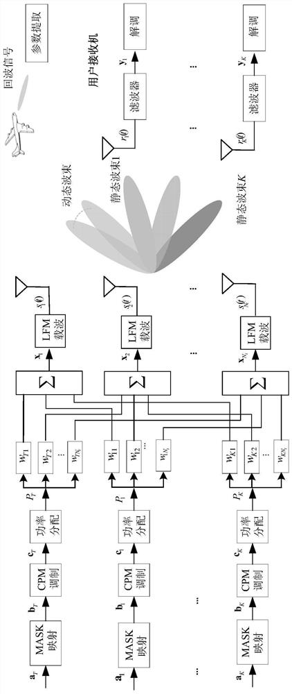
[0026] Embodiment 1: Combining figure 1 and figure 2 This embodiment will be described. The method for transmitting and receiving communication radar signals based on continuous phase modulation and chirp described in this embodiment includes the following steps:

[0027] Step 1, modulate the original data of each user and the target pilot sequence respectively to obtain the modulated data of each user and the target;

[0028] Step 2. According to the modulated data obtained in step 1, power is allocated to all users and targets, and the power P of each user is obtained. k and the target power P T ;

[0029] Step 3. According to the power of each user and target, obtain the baseband waveform signal formed by each user and target in the form of pulses, each baseband waveform signal is loaded on a chirp carrier signal to form a transmission signal, and use the antenna to transmit Going out, the transmission signal of the target is a dynamic beam transmission signal, and the...

specific Embodiment approach 2

[0043] Embodiment 2: This embodiment is a method for transmitting and receiving communication radar signals based on continuous phase modulation and chirp described in Embodiment 1. In step 1, the modulated data of each user and target is obtained, and the specific process is as follows:

[0044]The original data of each user and the target pilot sequence are mapped into mapped data by MASK, and the phase of each mapped data is modulated by CPM to obtain the phase information of each user and target. According to the phase information of each user and target Get the modulated data for each user and target.

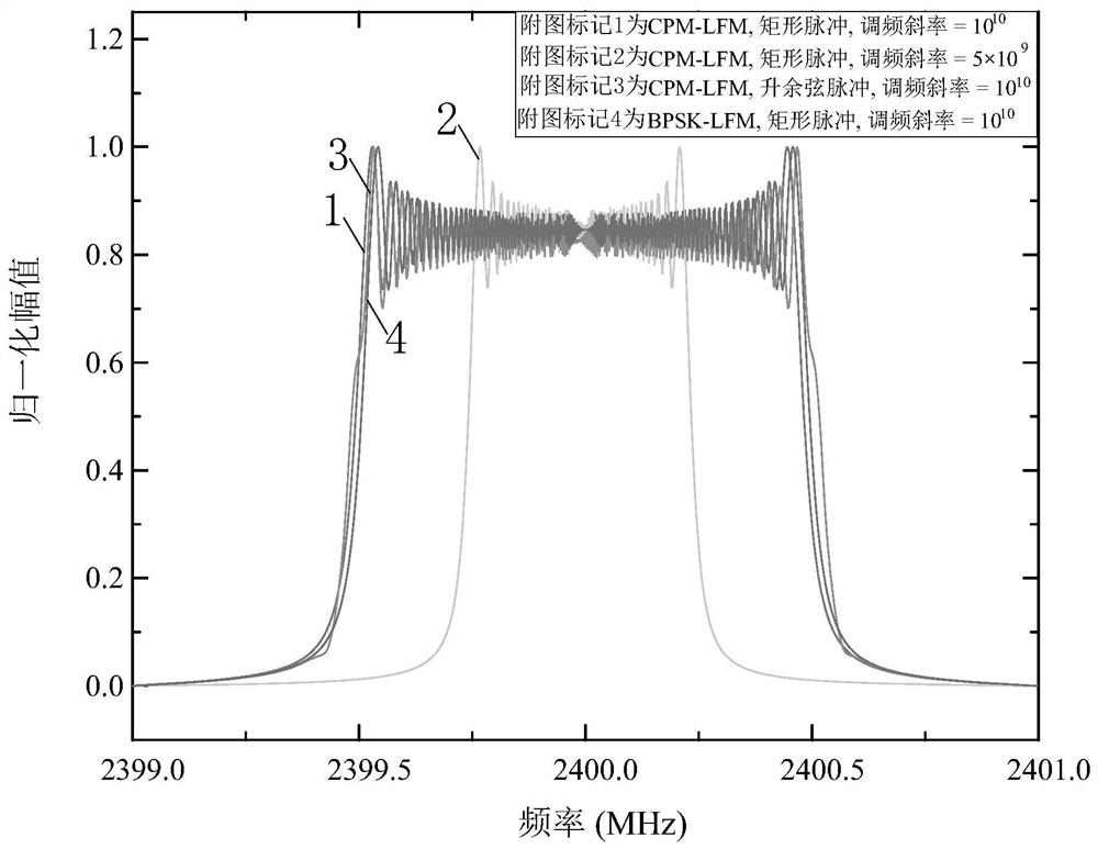
[0045] In this embodiment, figure 2 Give the CPM-BF-LFM signal spectrum, where BF represents multi-beam, referring to static beam and dynamic beam; MASK is multi-ary amplitude shift keying, BPSK is binary phase keying, CPM is continuous phase modulation, LFM is linear FM carrier, it can be seen that the signal spectrum is related to the modulation method, the transmissio...

specific Embodiment approach 3

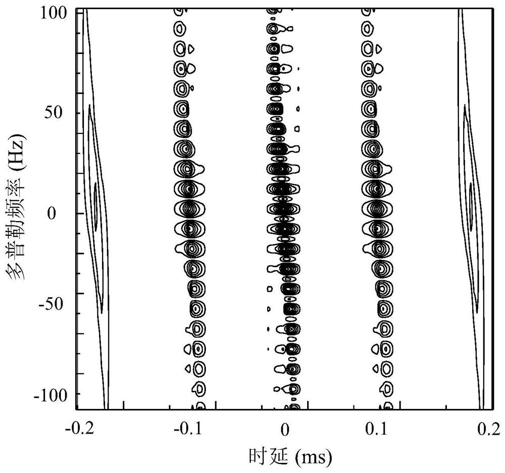
[0048] Embodiment 3: This embodiment is a method for transmitting and receiving communication radar signals based on continuous phase modulation and linear frequency modulation described in Embodiment 1. In step 4, the base station receiver obtains the position and the target position according to the echo signal. The specific process of speed is:

[0049] If the echo strength of the echo signal is higher than the threshold, it is determined that the target exists, and the echo signal and the chirp carrier signal are multiplied and processed by the low-pass filter at the base station to obtain the difference frequency signal of the rising edge and the falling edge. The beat frequency signal of the rising edge and the beat frequency signal of the falling edge are respectively extracted from the beat frequency signal of the rising edge and the beat frequency of the falling edge, and the target time delay and Doppler frequency are estimated, and then obtain The position and speed...


PUM


Abstract

A communication radar signal transceiving method based on continuous phase modulation and linear frequency modulation belongs to the field of signal modulation. The purpose of the present invention is to solve the problem that the existing communication radar integrated system can only realize the communication signal transmission function or the radar target detection function only, resulting in low spectrum utilization efficiency. This application combines traditional continuous phase modulation, beamforming and chirp signals. Considering the existence of interference, the multi-antenna beamforming scheme can be used to extract its own information at the user end. At the same time, at the base station end Through the processing of the echo, the time delay and Doppler information are extracted to realize the estimation of the target angle, distance and speed, and complete the multi-user data transmission and target detection. It is used to realize the function of communication signal transmission and radar target detection at the same time.

Description

technical field [0001] The invention relates to a communication radar integrated signal sending and receiving method, and belongs to the field of signal modulation. Background technique [0002] The communication radar integrated system depends on the high-quality communication and radar fusion design, so the design of the communication radar integrated signal becomes one of the key issues. However, the existing communication radar integrated system can only realize the communication signal transmission function or the radar target detection function, but cannot realize the communication signal transmission function and the radar target detection function at the same time, resulting in the problem of low spectrum utilization efficiency. SUMMARY OF THE INVENTION [0003] The purpose of the invention is to solve the problem that the existing communication radar integrated system can only realize the communication signal transmission function or the radar target detection fun...

Claims


Application Information

Patent Timeline
Patent Type & Authority Patents(China)
IPC IPC(8): H04L5/00G01S13/86H04B7/0426H04B7/0456H04L27/20
CPCH04L5/0048H04L27/20G01S13/86H04B7/043H04B7/0456
Inventor 曹宇于启月刘冠辰林泓池
Owner HARBIN INST OF TECH
Why Eureka
Try Eureka