Rotary compressor, method for manufacturing rotary compressor, and refrigeration cycle device

A technology of rotary compressor and rotary shaft, which is applied in the direction of rotary piston/oscillating piston pump components, rotary piston machinery, pump combinations for elastic fluid rotary piston/oscillating piston, etc., which can solve problems that cannot Get lubricating performance and other issues

Active Publication Date: 2021-09-14
TOSHIBA CARRIER CORP
View PDF6 Cites 0 Cited by
  • Summary
  • Abstract
  • Description
  • Claims
  • Application Information

AI Technical Summary

Problems solved by technology

However, if the refrigerant compressed by the compression mechanism enters the supply path, desired lubricating performance may not be obtained.

Method used


Image

  • Rotary compressor, method for manufacturing rotary compressor, and refrigeration cycle device
  • Rotary compressor, method for manufacturing rotary compressor, and refrigeration cycle device
  • Rotary compressor, method for manufacturing rotary compressor, and refrigeration cycle device

Examples


no. 1 Embodiment approach

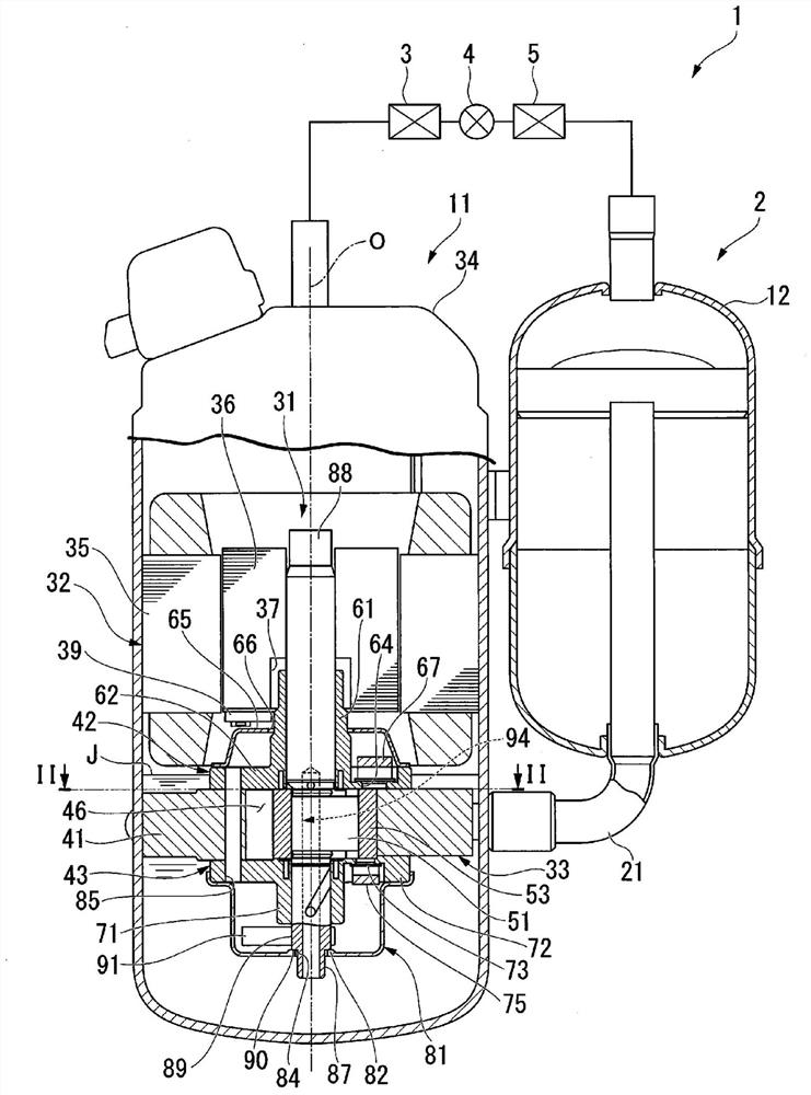
[0019] First, the refrigeration cycle device 1 will be briefly described. figure 1 It is a schematic configuration diagram of the refrigeration cycle apparatus 1 including a cross-sectional view of the rotary compressor 2 in the first embodiment.

[0020] Such as figure 1 As shown, the refrigeration cycle apparatus 1 of the present embodiment includes a rotary compressor 2, a condenser 3 as a radiator connected to the rotary compressor 2, an expansion device 4 connected to the condenser 3, and an expansion device connected to the expansion device. 4 and the evaporator 5 as a heat absorber between the rotary compressor 2.

[0021] The rotary compressor 2 is a so-called rotary compressor. The rotary compressor 2 compresses the low-pressure gas refrigerant taken inside to turn it into a high-temperature and high-pressure gas refrigerant. In addition, the specific structure of the rotary compressor 2 will be mentioned later.

[0022] The condenser 3 radiates heat from the high...

no. 2 Embodiment approach

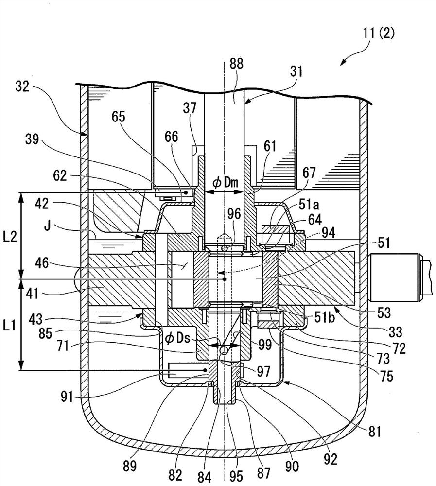
[0087] Figure 4 It is a partial sectional view of the rotary compressor 200 of 2nd Embodiment. In the following description, the same reference numerals are assigned to the same configurations as those in the above-mentioned embodiments, and description thereof will be omitted.

[0088] The difference between the rotary compressor 200 of this embodiment and the above-mentioned first embodiment is that a plurality of (for example, three) cylinders (upper cylinder 201, middle cylinder 202, and lower cylinder 203) are arranged along Axial arrangement.

[0089] exist Figure 4 In the rotary compressor 200 shown, the upper cylinder 201 and the intermediate cylinder 202 are butted in the axial direction with the upper partition 210 interposed therebetween. The middle cylinder 202 and the lower cylinder 203 are butted in the axial direction with the lower partition 211 interposed therebetween. In addition, the structure of each cylinder 201-203 is the same as that of the said em...


PUM


Abstract

This rotary compressor has a case, a rotating shaft, a compression mechanism, a balancer, and a balancer cover. A through-hole is formed at a position in the balancer cover that is facing the rotating shaft in the axial direction. The rotating shaft has a thrust sliding section, a protruding section, and a supply path. The thrust sliding section abuts a seal section positioned around the through-hole in the balancer cover, in the axial direction of the rotating shaft. The protruding section is positioned on the inner circumference side of the thrust sliding section and protrudes through the through-hole, to protrude further below the lower end of the through-hole. The supply path opens at the lower end face of the protruding section and guides lubricating oil.

Description

technical field [0001] Embodiments of the present invention relate to a rotary compressor, a method of manufacturing the rotary compressor, and a refrigeration cycle device. [0002] This application claims the priority of Japanese Patent Application No. 2019-020870 filed in Japan on February 7, 2019, and uses the content thereof here. Background technique [0003] Rotary compressors are used in refrigeration cycle devices such as air conditioners. In the rotary compressor, the eccentric portion of the rotary shaft rotates eccentrically in the compression mechanism portion, whereby the refrigerant is compressed. [0004] In such a rotary compressor, a supply path for supplying lubricating oil stored in the casing to a sliding portion between the rotary shaft and the bearing is formed in the rotary shaft. However, if the refrigerant compressed by the compression mechanism unit enters the supply path, desired lubricating performance may not be obtained. [0005] prior art l...

Claims


Application Information

Patent Timeline
IPC IPC(8): F04C29/02F04C18/356F04C23/02F04C29/00
CPCF04C18/356F04C23/008F04C2240/603F04C29/023F04C2240/807F04C2240/809F04C2230/60
Inventor 平山卓也长畑大志
Owner TOSHIBA CARRIER CORP
Why Eureka
Try Eureka