
Block bonding and combining equipment capable of accurately positioning, taking and placing lower plate

A combined equipment and precise positioning technology, which is applied in the direction of mechanical equipment, connecting components, object stacking, etc., can solve problems that affect the accuracy of bonding combination and cannot ensure the accuracy of the lower plate

Inactive Publication Date: 2021-09-17
长沙市雄武自动化设备有限公司
View PDF0 Cites 0 Cited by
  • Summary
  • Abstract
  • Description
  • Claims
  • Application Information

AI Technical Summary

Problems solved by technology

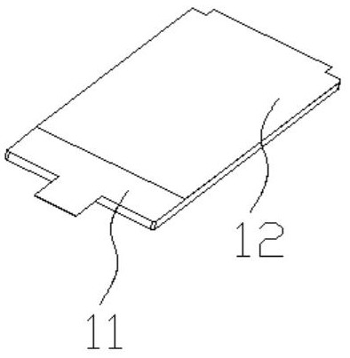
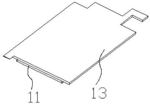
[0002] like image 3 As shown, it is a combination block, including a lower plate 11 and an upper plate 13, and its lower plate 11 and upper plate 13 are adhesively bonded, and the lower plate 11 is as follows before assembly figure 2 As shown, its upper surface is covered with film 12, the film needs to be removed (removed) first, so that its upper surface has a bonding function, and then the upper plate 13 is placed on the lower plate 11. To perform automated assembly, it is necessary to Automatic feeding of the lower board is realized. Most of the existing feeding is a feeding manipulator, which uses multi-axis motion to realize the feeding. However, the multi-axis motion cannot ensure the accuracy of the lower board after discharging, so it will affect the subsequent bonding. Combined accuracy

Method used


Image

  • Block bonding and combining equipment capable of accurately positioning, taking and placing lower plate
  • Block bonding and combining equipment capable of accurately positioning, taking and placing lower plate
  • Block bonding and combining equipment capable of accurately positioning, taking and placing lower plate

Examples


Embodiment Construction

[0026] In order to enable those skilled in the art to better understand the technical solution of the present invention, the present invention will be described in detail below in conjunction with the accompanying drawings. The description in this part is only exemplary and explanatory, and should not have any limiting effect on the protection scope of the present invention. .

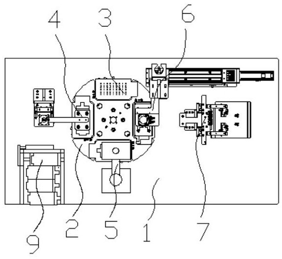
[0027] Such as Figure 1-3 and Figure 5-6 As shown, the specific structure of the present invention is: a block bonding combination equipment capable of accurately positioning and placing the lower plate, including a frame 1, and the frame 1 is provided with a turntable 2 equipped with a driving structure. The above-mentioned turntable 2 is evenly provided with carriers 3, and the frame 1 is sequentially provided with a lower plate discharge device 4 docked with the carrier 3, a film removal device 5 and an upper plate discharge device along the rotation direction of the turntable 2. material device...


PUM


Abstract

The invention relates to block bonding and combining equipment capable of accurately positioning, taking and placing a lower plate. The equipment comprises a rack; a turntable is arranged on the rack; carriers are uniformly arranged on the turntable; a lower plate discharging device, a film removing device and an upper plate discharging device which are in butt joint with the carriers are sequentially arranged on the rack in the rotating direction of the turntable; the rack is further provided with a lower plate conveying device matched with the lower plate discharging device; the lower plate conveying device comprises a lower plate conveying groove formed in the rack; a lower plate intercepting block is arranged at the tail end of the lower plate conveying groove; a lower plate clamping air cylinder perpendicular to the lower plate conveying groove is arranged on the outer side of the lower plate intercepting block; the lower plate clamping air cylinder is connected with a lower plate clamping movable block; the lower plate clamping movable block is connected with a lower plate clamping connecting rod capable of penetrating into the lower plate conveying groove; the lower plate clamping connecting rod is connected with a lower plate clamping block matched with the lower plate; and the other side wall of the lower plate clamping block and the other side wall of the lower plate conveying groove are both lower than the lower plate in the lower plate conveying groove. The precision control difficulty is reduced.

Description

technical field [0001] The invention relates to the field of assembly equipment, in particular to a block bonding combination equipment capable of accurately positioning and taking out a lower plate. Background technique [0002] Such as image 3 As shown, it is a combination block, including a lower plate 11 and an upper plate 13, and its lower plate 11 and upper plate 13 are adhesively bonded, and the lower plate 11 is as follows before assembly figure 2 As shown, its upper surface is covered with film 12, the film needs to be removed (removed) first, so that its upper surface has a bonding function, and then the upper plate 13 is placed on the lower plate 11. To perform automated assembly, it is necessary to Automatic feeding of the lower board is realized. Most of the existing feeding is a feeding manipulator, which uses multi-axis motion to realize the feeding. However, the multi-axis motion cannot ensure the accuracy of the lower board after discharging, so it will af...

Claims


Application Information

Patent Timeline
IPC IPC(8): B65G61/00B65G57/04B65G47/91F16B11/00B66F3/24
Inventor 卢本雄郑艺旋
Owner 长沙市雄武自动化设备有限公司
Learn More