Conductive nozzle punching machine feeding system

A technology of feeding system and punching machine, applied in metal processing and other directions, can solve the problem of low degree of automation, and achieve the effects of liberating labor, improving cleanliness, and improving movement stability

Active Publication Date: 2017-01-18
CHANGZHOU YI WIDE AUTOMATION EQUIP CO LTD
View PDF7 Cites 0 Cited by
  • Summary
  • Abstract
  • Description
  • Claims
  • Application Information

AI Technical Summary

Problems solved by technology

However, operators are still required to load and pick up parts, and the degree of automation is not high

Method used


Image

  • Conductive nozzle punching machine feeding system
  • Conductive nozzle punching machine feeding system
  • Conductive nozzle punching machine feeding system

Examples


Embodiment Construction

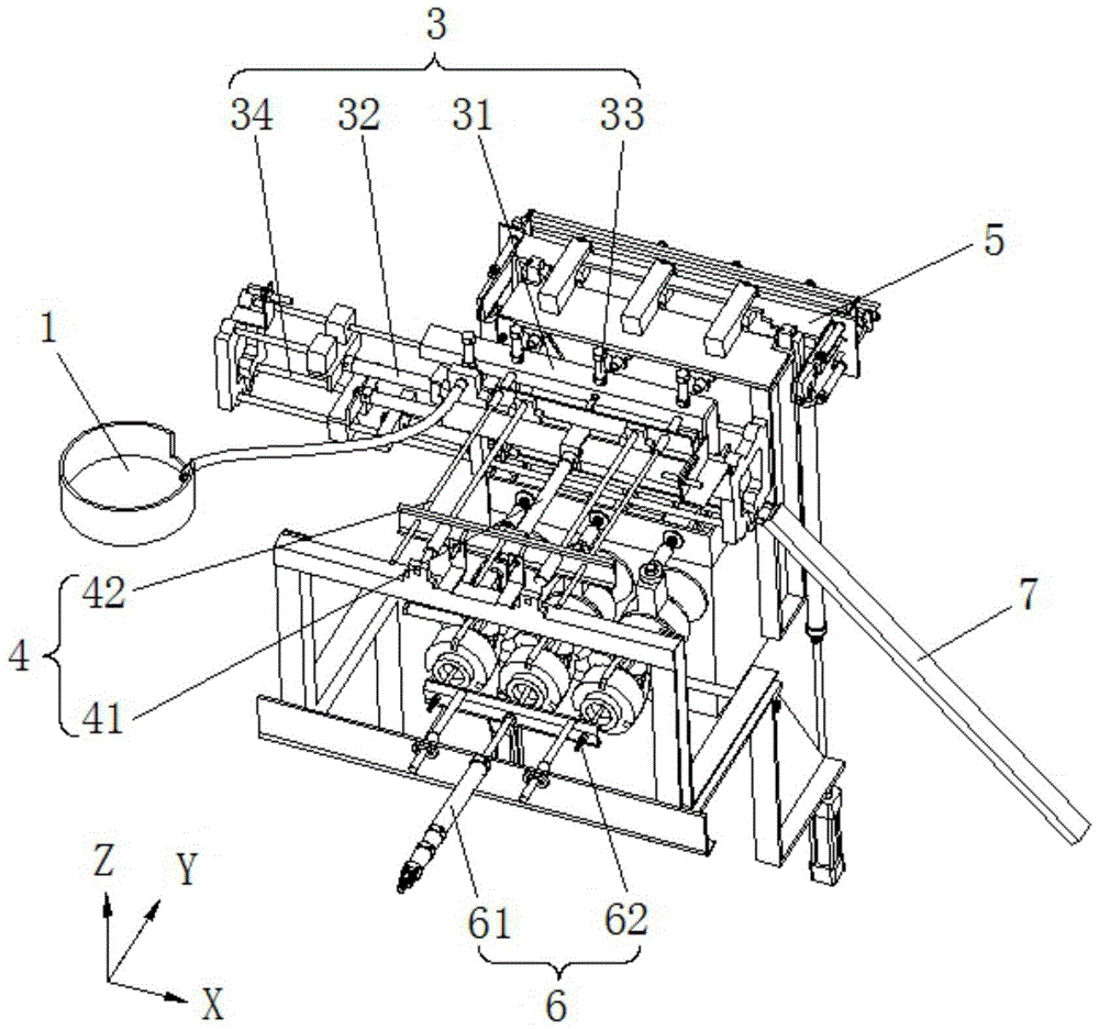
[0026] See Figure 1 to Figure 8 , the present invention includes a frame and a processing spindle, the processing spindle is provided with a processing hole for clamping workpieces; it also includes a feeding port fixed on the frame, an induction head 2, a charging unit 3, and a first ejection assembly 4. The transfer unit 5, the second ejector assembly 6 and the aggregate assembly 7; the feeding port is set opposite to the induction head 2, and the feeding port is provided with a first locking device 11 that can limit the discharge; The feeding port is connected with the discharge end of the vibrating plate.

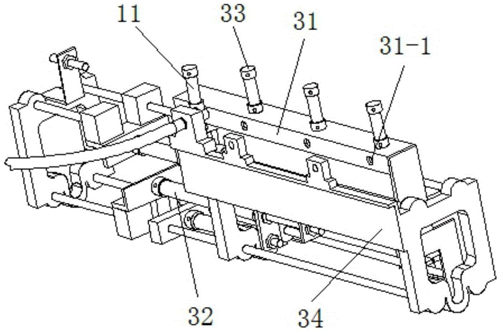
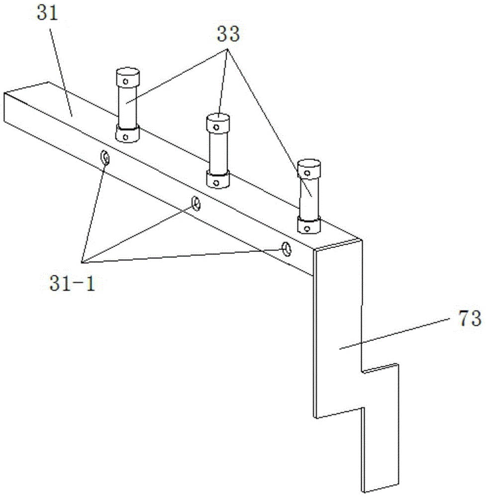
[0027]The charging unit 3 includes a charging rack 31, a charging cylinder 32, a charging skid 34 and a slider; above; the charging rack 31 is fixedly arranged on the slider, the charging cylinder 32 is fixedly arranged on the charging slide frame 34, and the output shaft of the charging cylinder 32 is fixedly connected with the slider; the charging rack 31 is located...


PUM


Abstract

The invention relates to a contact tube perforating machine feeding system which comprises a machine frame, a machining spindle, a vibration disc and an induction head, a loading unit, a first ejection assembly, a transfer unit, a second ejection assembly and a material collection assembly. A machining hole used for clamping workpieces is formed in the machining spindle, a feeding port of the vibration disc is arranged opposite to the induction head of the feeding port, the charging unit is arranged between the feeding port and the induction head, and the transfer unit is arranged on one side of the charging unit. The workpieces are charged into the charging unit through the vibration disc and transferred into the transfer unit through the first ejection assembly, then moved into the machining spindle through the transfer unit to be machined and finally placed into the material collection assembly through the second ejection assembly and the transfer unit. The contact tube perforating machine feeding system is high in automation degree, capable of machining workpieces simultaneously, greatly improves production efficiency and reduces production cost.

Description

technical field [0001] The invention relates to the field of conductive tip processing machinery, in particular to a feeding system for a conductive tip punching machine. Background technique [0002] The contact tip is a consumable part of welding equipment and belongs to welding consumables. At the end of the welding torch, the metal tip used to guide the welding wire is the conductive tip. The contact tip is generally made of copper (brass, copper, etc.). The contact tip will go through the drilling step during processing. The traditional punching method is usually manually punched by the operator and can not punch multiple workpieces at the same time, so there is a lot of room for improvement in production efficiency. At the same time, the traditional punching method requires a lot of labor, which greatly increases the production cost. [0003] In order to improve production efficiency, some special punching machines for contact tips that can simultaneously punch mul...

Claims


Application Information

Patent Timeline
Patent Type & Authority Patents(China)
IPC IPC(8): B23Q7/00
CPCB23Q7/00B23Q7/006B23Q7/08
Inventor 徐峰
Owner CHANGZHOU YI WIDE AUTOMATION EQUIP CO LTD
Why Eureka
Try Eureka