
Double-layer high-pressure jet grouting diaphragm wall inner clamping vertical plastic laying device and construction method thereof

A technology of high-pressure rotary spraying and vertical plastic laying, which is applied in the direction of construction, earth mover/excavator, etc. It can solve the problems of reducing the efficiency of grooves with different widths, so as to improve the efficiency of grooves, improve the effect of grooves, Increase the effect of the width range

Active Publication Date: 2021-09-17
泰贻建设集团有限公司
View PDF17 Cites 0 Cited by
  • Summary
  • Abstract
  • Description
  • Claims
  • Application Information

AI Technical Summary

Problems solved by technology

[0004] In view of the related technologies mentioned above, the inventor believes that there are the following technical defects: when it is necessary to groove grooves of different widths, it is necessary to take out the entire plastic laying machine from the formed grooves, and re-use the plastic laying machine to correct the formed grooves. Multiple width expansions reduce the efficiency of slotting for grooves of different widths

Method used


Image

  • Double-layer high-pressure jet grouting diaphragm wall inner clamping vertical plastic laying device and construction method thereof
  • Double-layer high-pressure jet grouting diaphragm wall inner clamping vertical plastic laying device and construction method thereof
  • Double-layer high-pressure jet grouting diaphragm wall inner clamping vertical plastic laying device and construction method thereof

Examples


Embodiment Construction

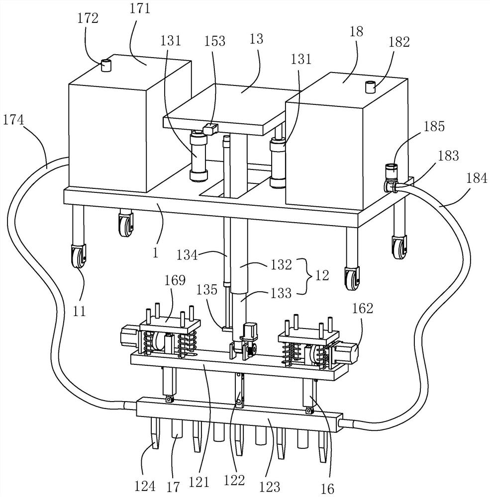
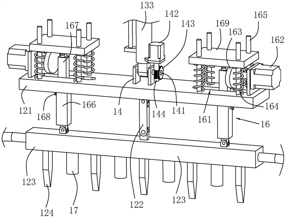
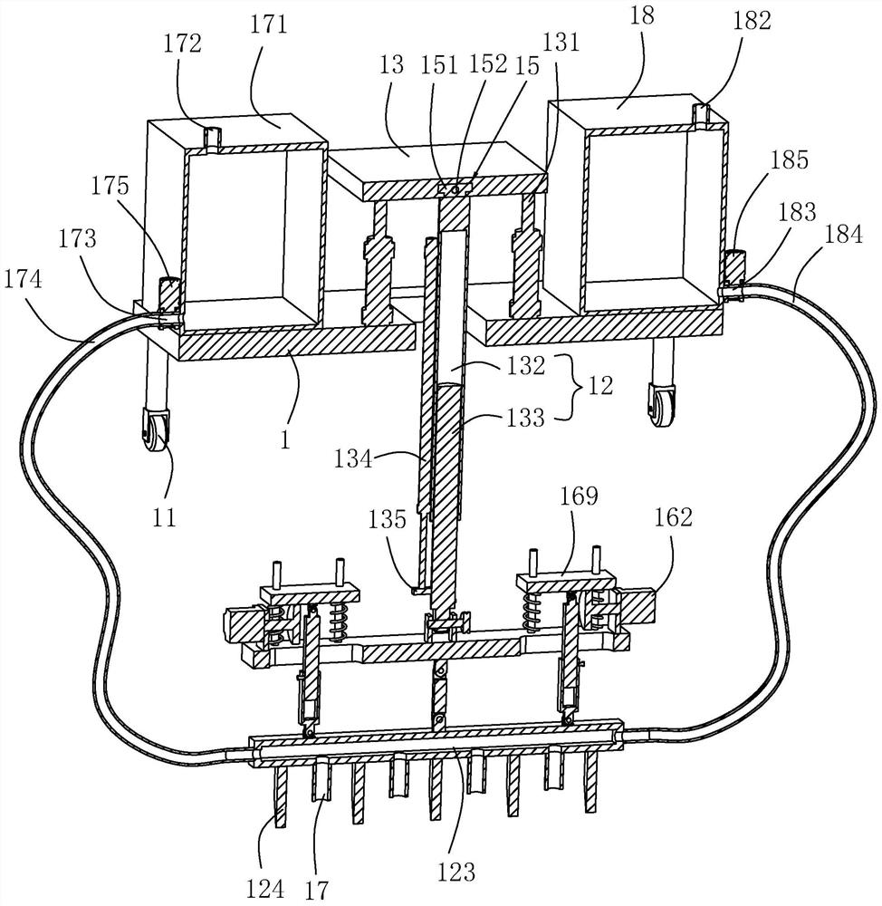
[0040] The following is attached Figure 1-3 The application is described in further detail.

[0041] The embodiment of the present application discloses a vertical plastic laying device for double-layer high-pressure rotary spraying anti-seepage walls. refer to figure 1 , a double-layer high-pressure rotary spray anti-seepage wall clamping vertical plastic laying device, comprising a moving plate 1, rollers 11 are arranged under the moving plate 1 and located at the four corners of the moving plate 1, a rod body 12 is pierced on the moving plate 1, and the rod body 12 The end portion below the moving plate 1 is provided with a mounting rod 121, the mounting rod 121 is hingedly provided with a hinged rod 122 on the surface away from the rod body 12, and the end of the hinged rod 122 away from the mounting rod 121 is hingedly provided with a connecting rod 123, and the connecting rod 123 away from the face of the mounting rod 121 along the length direction of the connecting r...


PUM


Abstract

The invention relates to a double-layer high-pressure jet grouting diaphragm wall inner clamping vertical plastic laying device which comprises a moving plate. Rolling wheels are arranged below the moving plate, a rod body is arranged on the moving plate in a penetrating mode, a mounting rod is arranged at the end, located below the moving plate, of the rod body, a hinge rod is hinged to the face, away from the rod body, of the mounting rod, a connecting rod is hinged to the end, away from the mounting rod, of the hinge rod, and a plurality of grooving cutters are evenly arranged on the face, away from the mounting rod, of the connecting rod in the length direction of the connecting rod; hinging plates are arranged on the mounting rod and located on the two sides of the rod body, a hinging shaft penetrating through the rod body and rotatably connected to the rod body is fixedly arranged between the hinging plates on the two sides, the length direction of the hinging shaft is parallel to the length direction of the connecting rod, and a first driving device used for driving the hinging shaft to drive the mounting rod to swing in a reciprocating mode is arranged on the rod body; and a second driving device for driving the connecting rod to swing back and forth at a hinge point is arranged on the mounting rod. The double-layer high-pressure jet grouting diaphragm wall inner clamping vertical plastic laying device has the advantage that the grooving efficiency of grooves with different widths is improved.

Description

technical field [0001] The application relates to the field of anti-seepage construction, in particular to a vertical plastic-laying device and a construction method for double-layer high-pressure rotary spraying anti-seepage walls. Background technique [0002] The working principle of the vertical film laying technology is to use a special trenching and trenching machine to open a trench with a certain width and depth, lay a plastic film in the trench, and then fill it with backfill soil to form an anti-seepage with the plastic film as the main body. The curtain acts as an anti-seepage effect. [0003] The Chinese patent application publication number CN105735392A discloses a hydraulic vertical film laying machine, which includes a plastic film roll, a plastic film inner rod in the plastic film roll, a plastic film base at the lower end of the inner rod, and a hydraulic oil pump on the panel. The upper end of the steel pipe is connected to the panel, the lower end of the ...

Claims


Application Information

Patent Timeline
Patent Type & Authority Applications(China)
IPC IPC(8): E02F5/02
CPCE02F5/02
Inventor 杨佳李佳
Owner 泰贻建设集团有限公司
Learn More