Signal encodnig device and method

A signal coding and equipment technology, applied in image coding, digital video signal modification, pulse modulated TV signal transmission, etc., can solve problems such as unsatisfactory, frequent wrong selection of inefficient coding types, etc., and achieve the effect of improving coding efficiency

Inactive Publication Date: 2004-01-07
SONY CORP
View PDF0 Cites 1 Cited by
  • Summary
  • Abstract
  • Description
  • Claims
  • Application Information

AI Technical Summary

Problems solved by technology

However, this method is unsatisfactory for estimating the DCT coding efficiency of each 8×8 data block
That is, Model 3 misselec

Method used


Image

  • Signal encodnig device and method
  • Signal encodnig device and method
  • Signal encodnig device and method

Examples


Embodiment Construction

[0038] FIG. 3 schematically shows an example of the structure of a moving picture encoding device adopting the moving picture encoding method of the present invention in the form of a block diagram. As shown in the figure, the moving picture image signal S1 provided at the terminal 10 passes through a calculator 11 for providing a prediction residual to a DCT encoder constituting a DCT circuit 12, a quantization circuit 13, an inverse quantization circuit 14, and an inverse quantization circuit 14. DCT circuit 15 , calculator 16 and motion compensation circuit 17 . The DCT encoder will be further described below.

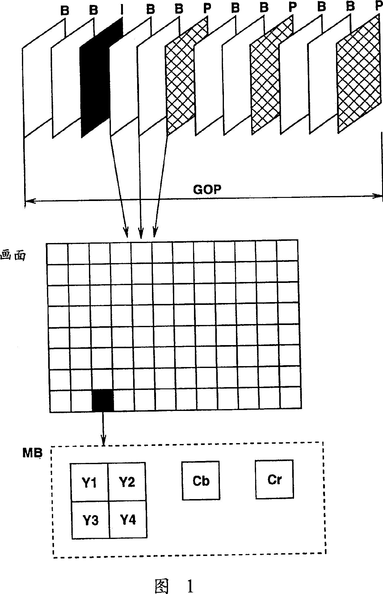
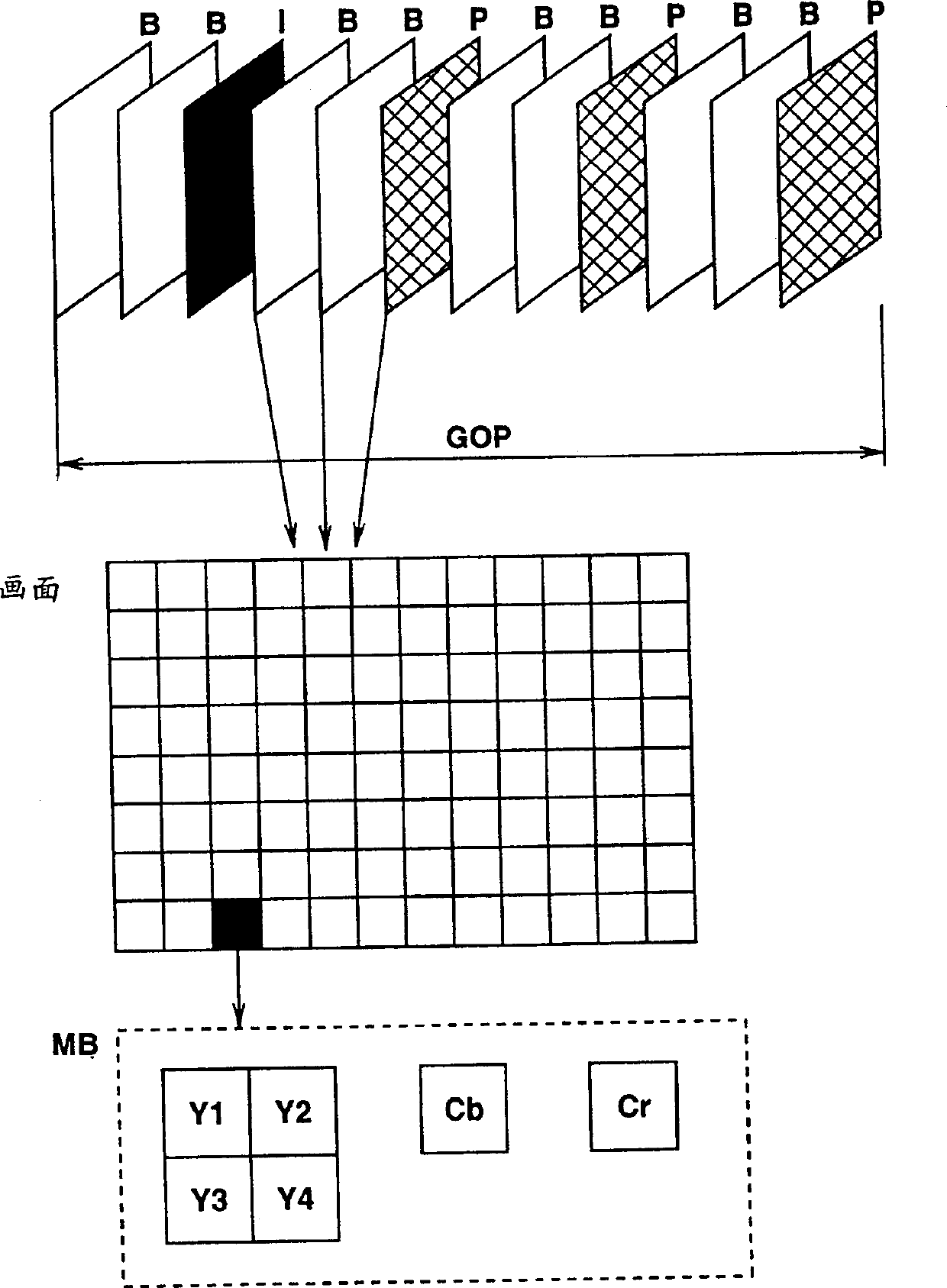
[0039] The moving picture image signal S1 supplied at the terminal 10 is also supplied to a motion vector detection / motion prediction residual calculation circuit 21 . In this circuit 21, pattern matching is performed between a reference frame and an input MB (macroblock) luminance signal to detect a motion vector of the input MB. That is, on the basis of the foll...


PUM


Abstract

A signal coding apparatus and method, a signal recording medium and a signal transmitting method is disclosed in which a motion-picture image signal supplied at an input terminal is delivered to a motion vector detection/motion-prediction residual calculator, intra-image motion-prediction residual calculator, and to an frame/field DCT coding type judging means. In the frame/field DCT type judging means, the type of DCT coding is judged for the input MB (macro block). Based on the DCT coding type, the intra-image motion-prediction residual is calculated by the intra-image motion-prediction residual calculator. The intra-image motion-prediction residual thus obtained and input MB motion-prediction residual as compared with each other by the INTRA/INTER judging means to judge whether the input MB is to be intra- or inter-coded. The intra- or inter-coding is done in the decided coding mode.

Description

technical field [0001] The present invention relates to a signal encoding device and method, a signal recording medium and a signal transmission method, and in particular to a method suitable for recording moving picture image signals on recording media such as optical disks, magnetic tapes, etc. A signal coding device and method for displaying on a display unit, a signal recording medium, and a signal transmission method, and particularly relates to a method suitable for use in teleconferencing systems (video conferencing systems), screen telephone systems (video telephone systems), broadcasting systems, etc. A signal encoding device and method, a signal recording medium, and a signal transmission method for transmitting a moving picture image signal from a sender to a receiver through a transmission line. Background technique [0002] Since digital video signals have a large amount of data, recording digital video signals on a recording medium with a small capacity for a l...

Claims


Application Information

Patent Timeline
IPC IPC(8): H04N5/92G06T9/00H04N19/107H04N19/119H04N19/12H04N19/137H04N19/176H04N19/186H04N19/196H04N19/50H04N19/51H04N19/60H04N19/625H04N19/91
CPCH04N19/00781H04N19/0003H04N7/26031H04N7/50H04N7/5086H04N19/61H04N19/107
Inventor 加藤元树
Owner SONY CORP
Why Eureka
Try Eureka