Method for reducing high-frequency noise of board-level DC-DC switching power supply

A technology of switching power supply and high-frequency noise, which is applied in the direction of electrical components, adjusting electric variables, and output power conversion devices, etc., which can solve the problems of strong high-frequency noise, influence, and difficulty in applying to integrated electronic equipment, etc., to achieve reduction Effect of High Frequency Radiated Noise

Inactive Publication Date: 2021-09-21
西安超越申泰信息科技有限公司
View PDF3 Cites 0 Cited by
  • Summary
  • Abstract
  • Description
  • Claims
  • Application Information

AI Technical Summary

Problems solved by technology

[0002] DC-DC switching power supply has many advantages such as small footprint, high conversion efficiency, low power consumption, and wide voltage regulation range. It is favored in highly integrated and miniaturized electronic equipment, and is widely used in industrial control, military industry, and communication. And power and other fields, but DC-DC switching power supply will generate strong high-frequency noise, which will affect other components in the same system. The main reason is that fast switching currents will be generated in the switching path, and these switching currents are very large , will generate a strong alternating magnetic field
[0003] The traditional way to reduce the noise of switching power supply is to add LC filter circuit at its input / output end and reduce the change rate of PWMMOS gate signal
[0004] There are two main disadvantages of adding an LC filter circuit at the input / output end: one is that it will increase the board area of ​​the DC-DC switching power supply circuit, and it is difficult to apply it to electronic equipment with a high degree of integration.
Second, it will affect the load transient response of the DC-DC switching power supply circuit, and affect the working stability of ICs such as FPGA and CPU. The power supply requirements of such ICs are small voltage and high current, which have high requirements for transient power supply capability.
[0005] The main disadvantage of reducing the change rate of the PWM MOS gate signal is that it will increase the switching loss and seriously reduce the conversion efficiency of the switching power supply.
[0006] It can be seen that these two methods will increase the board area, affect the transient response of the load, and reduce the conversion efficiency. For highly integrated and miniaturized electronic equipment, the advantages outweigh the disadvantages.

Method used


Image

  • Method for reducing high-frequency noise of board-level DC-DC switching power supply

Examples


Embodiment Construction

[0021] In order to enable those skilled in the art to better understand the solutions of the present invention, the present invention will be further described in detail below in conjunction with specific embodiments. Apparently, the described embodiments are only some of the embodiments of the present invention, but not all of them. Based on the embodiments of the present invention, all other embodiments obtained by persons of ordinary skill in the art without making creative efforts fall within the protection scope of the present invention.

[0022] A preferred embodiment is given below:

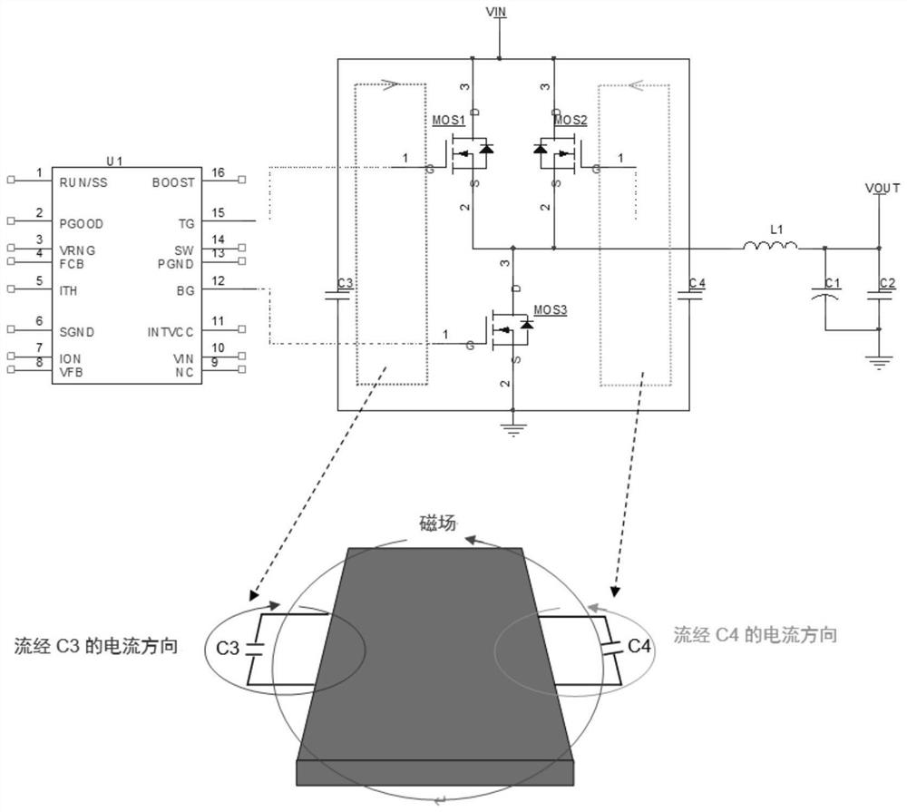
[0023] Such as figure 1 As shown, a method for reducing the high-frequency noise of a board-level DC-DC switching power supply in this embodiment is to divide a single switching MOS (that is, a PWM MOS) at the High-Side end into two other symmetrical switching loops, and one switching loop is composed of Composed of MOS1, MOS3 and capacitor C3; another switch loop is composed of MOS2, MO...


PUM


Abstract

The invention relates to the technical field of power supply control, in particular to a method for reducing high-frequency noise of a board-level DC-DC switching power supply. The method is characterized in that a single switch MOS at a High-Side end is divided into two symmetrical switch loops, and one switch loop consists of an MOS1, an MOS3 and a capacitor C3; and the other switch loop consists of an MOS2, an MOS3 and a capacitor C4. Compared with the prior art, the PWM switching circuit of the DC-DC switching power supply is divided into another two symmetrical switching circuits, so that an alternating magnetic field generated by the switching circuits is limited in an area close to a PWM control chip, the high-frequency radiation noise of the switching power supply is reduced, and the method has good popularization value.

Description

technical field [0001] The invention relates to the technical field of power supply control, and specifically provides a method for reducing high-frequency noise of a board-level DC-DC switching power supply. Background technique [0002] DC-DC switching power supply has many advantages such as small footprint, high conversion efficiency, low power consumption, and wide voltage regulation range. It is favored in highly integrated and miniaturized electronic equipment, and is widely used in industrial control, military industry, and communication. And power and other fields, but DC-DC switching power supply will generate strong high-frequency noise, which will affect other components in the same system. The main reason is that fast switching currents will be generated in the switching path, and these switching currents are very large , will generate a strong alternating magnetic field. [0003] The traditional way to reduce the noise of switching power supply is to add LC fi...

Claims


Application Information

Patent Timeline
Patent Type & Authority Applications(China)
IPC IPC(8): H02M1/44H02M3/158
CPCH02M1/44H02M3/158
Inventor 徐成焱吴之光戴晓龙
Owner 西安超越申泰信息科技有限公司
Why Eureka
Try Eureka