
Siphon treatment pipeline sludge clearing system

A technology of cleaning system and siphon tube, which is applied in the field of siphon treatment pipeline sludge cleaning system and pipeline cleaning device, which can solve the problems of mud pump or water pump damage, affecting the normal drainage of domestic sewage and rainwater, and inability to clean municipal pipelines, etc., to achieve the goal of reducing waste Effect

Inactive Publication Date: 2021-09-24
唐友慧
View PDF7 Cites 1 Cited by
  • Summary
  • Abstract
  • Description
  • Claims
  • Application Information

AI Technical Summary

Problems solved by technology

[0002] Municipal pipelines are used to discharge domestic sewage generated in people's daily life or rainwater in rainy weather. When sewage or rainwater is discharged into municipal pipelines, a large amount of dust will be carried. Over time, these dusts accumulate inside municipal pipelines to form sludge , so that the inner diameter of the municipal pipeline will be reduced, which will affect the normal drainage of domestic sewage or rainwater, so people need to regularly clean up the accumulated silt inside the municipal pipeline
[0003] When cleaning sludge in traditional municipal pipelines, mud pumps and water pumps are often used to clean the sludge inside municipal pipelines, but mud pumps cannot pump out all the sludge inside municipal pipelines, and the inner walls of municipal pipelines will still Sludge adheres, so that the municipal pipeline cannot be fully cleaned, and the length of the municipal pipeline is too long, so the workload of the mud pump and water pump is relatively large, which can easily lead to damage to the mud pump or water pump, which will increase cleaning. cost

Method used


Image

  • Siphon treatment pipeline sludge clearing system
  • Siphon treatment pipeline sludge clearing system
  • Siphon treatment pipeline sludge clearing system

Examples


Embodiment Construction

[0034] The following will clearly and completely describe the technical solutions in the embodiments of the present invention with reference to the accompanying drawings in the embodiments of the present invention. Obviously, the described embodiments are only some, not all, embodiments of the present invention. Based on the embodiments of the present invention, all other embodiments obtained by persons of ordinary skill in the art without making creative efforts belong to the protection scope of the present invention.

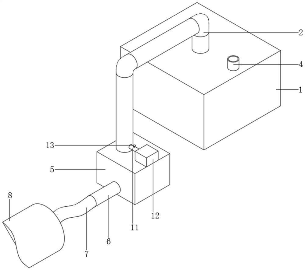
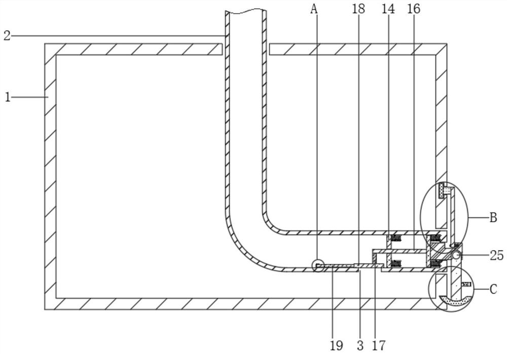
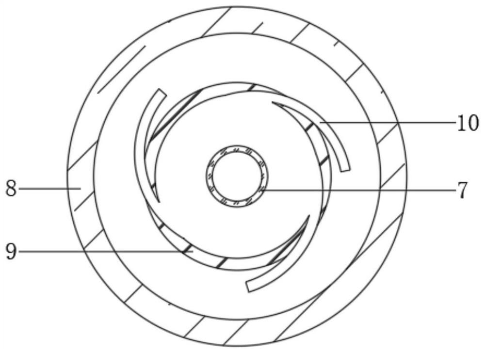
[0035] see Figure 1-8 As shown, a siphon treatment pipeline sludge cleaning system includes a water storage tank 1, a sludge pipeline 8, a cleaning device, a horizontal displacement device and a locking device. There is a siphon port 3 on the side, and the upper surface of the water storage tank 1 is fixedly connected with a water supply pipe 4, which is used to fill the interior of the water storage tank 1 with water flow. The hose 7 has no elasticity, so t...


PUM


Abstract

The invention discloses a siphon treatment pipeline sludge clearing system. The system comprises a water storage tank, a sludge pipeline, a clearing device, a horizontal shifting device and a locking device, a siphon pipe is arranged in the water storage tank in a sleeved mode, a siphon opening is formed in one side of the siphon pipe, an external hose is arranged in the sludge pipeline in a sleeved mode, one end of the external hose is fixedly connected with a water outlet pipe, one end of the water outlet pipe is fixedly provided with a transfer box, the clearing device is arranged in the sludge pipeline, the horizontal shifting device is arranged in the siphon pipe, the output end of the horizontal shifting device is connected with a sealing plate, the position of the sealing plate is controlled through the horizontal shifting device, and the locking device is arranged on one side of the water storage tank. The system has the beneficial effects that by means of the arrangement of the siphon pipe, water flow in the water storage tank is pumped out through the siphon effect of the siphon pipe, use of a water pump is reduced, and meanwhile the water flow can enter the external hose through the siphon pipe at a constant speed.

Description

technical field [0001] The invention relates to a pipeline cleaning device, in particular to a siphon treatment pipeline sludge cleaning system, which belongs to the technical field of pipeline cleaning. Background technique [0002] Municipal pipelines are used to discharge domestic sewage generated in people's daily life or rainwater in rainy weather. When sewage or rainwater is discharged into municipal pipelines, a large amount of dust will be carried. Over time, these dusts accumulate inside municipal pipelines to form sludge , so that the inner diameter of the municipal pipeline will be reduced, which will affect the normal drainage of domestic sewage or rainwater. Therefore, people need to regularly clean up the accumulated silt inside the municipal pipeline. [0003] When cleaning sludge in traditional municipal pipelines, mud pumps and water pumps are often used to clean the sludge inside municipal pipelines, but mud pumps cannot pump out all the sludge inside munic...

Claims


Application Information

Patent Timeline
Patent Type & Authority Applications(China)
IPC IPC(8): E03F9/00E03F5/20E03B11/00
CPCE03F9/00E03F5/20E03B11/00E03F9/007
Inventor 唐友慧
Owner 唐友慧
Learn More