
Lock catch device

A lock device and lock technology, applied in the field of locks, can solve the problems of uneven force on one side lock, limited tensile force, uneven force on the lock, etc., so as to increase the scope of application, improve the performance, lock The effect of uniform buckle force

Active Publication Date: 2021-09-24
SHANGHAI ONE TOP
View PDF36 Cites 1 Cited by
  • Summary
  • Abstract
  • Description
  • Claims
  • Application Information

AI Technical Summary

Problems solved by technology

[0006] In order to solve the technical problem that when the lock buckle is subjected to external force mentioned in the background technology, the uneven force on one side of the lock buckle is likely to cause distortion and deformation, and the technical problem of limited tensile force is provided. The problem of uneven force

Method used


Image

  • Lock catch device
  • Lock catch device
  • Lock catch device

Examples


Embodiment Construction

[0044] In order to make the purpose, technical solutions and advantages of the embodiments of the present invention clearer, the technical solutions in the embodiments of the present invention will be clearly and completely described below in conjunction with the drawings in the embodiments of the present invention. Obviously, the described embodiments It is a part of embodiments of the present invention, but not all embodiments. Based on the embodiments of the present invention, all other embodiments obtained by those skilled in the art without creative efforts fall within the protection scope of the present invention.

[0045] The technical features involved in different embodiments of the present invention described below may be combined with each other as long as they do not constitute a conflict with each other.

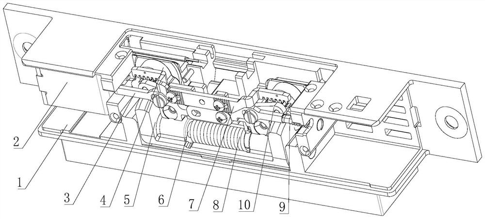
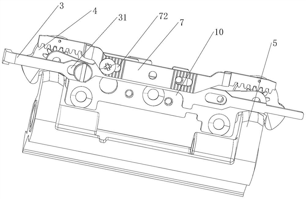
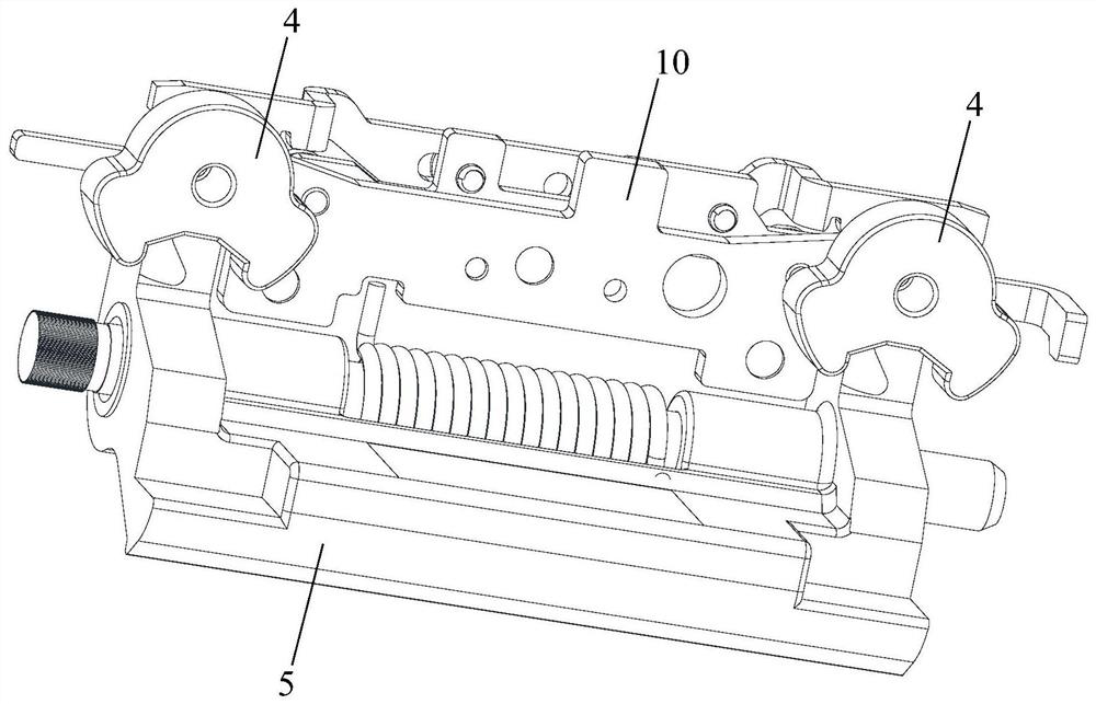
[0046] Refer to the attached figure 1 to attach Figure 18 The locker of the present invention is described.

[0047] The locking device in the present inven...


PUM


Abstract

The invention discloses a lock catch device. The lock catch device comprises a lock catch and at least two brake blocks, at least two brake parts are arranged on the lock catch, the brake parts on the lock catch correspond to the brake blocks, the brake blocks are connected with linkage pieces, and the linkage pieces can drive the brake blocks to rotate so that the brake blocks can abut against or be separated from the brake parts on the lock catch. According to the lock catch device, the brake blocks are symmetrically arranged at the two ends of the lock catch, when the lock catch is locked, the brake parts arranged at the two ends of the lock catch make contact with a main shaft, the lock catch is even in stress and does not distort, the service life of the lock catch device is prolonged, the lock catch device can be used in different stress environments, the application range of the lock catch device is widened, and the lock catch with stress on two sides can bear a relatively large dynamic impact test.

Description

technical field [0001] The invention belongs to the technical field of locks, in particular to a locking device. Background technique [0002] When the existing door body is in the closed state, the door lock is installed on the door panel, and the bolt on the door lock enters the groove of the lock catch device, and the lock catch fixes the lock tongue. The most common way in real life is to use a key to open the door. , retract the deadbolt by using the key. However, after the electronically controlled locking device is installed, the lock of the locking device can also be released by energizing and opening, and the door can be pushed open without the need of retracting the dead bolt. [0003] In the existing energized locking device, a transmission mechanism and a brake shaft are installed on the lock housing, and the transmission mechanism drives the brake shaft to move laterally, so that the lockset has the function of locking or unlocking. [0004] However, when the ...

Claims


Application Information

Patent Timeline
Patent Type & Authority Applications(China)
IPC IPC(8): E05B15/02
CPCE05B15/022E05B15/024Y02T10/7072
Inventor 张致维
Owner SHANGHAI ONE TOP
Learn More