Heat exchange fin, heat exchanger and air conditioner

A technology of heat exchange fins and heat exchangers, which is applied in the fields of heat exchange fins, heat exchangers and air conditioners, can solve the problems of low heat exchange efficiency of heat exchange fins, improve the heat exchange effect and improve the whole year. Coefficient of performance, the effect of avoiding the accumulation of water bridges

Pending Publication Date: 2021-09-24
GREE ELECTRIC APPLIANCES INC
View PDF0 Cites 0 Cited by
  • Summary
  • Abstract
  • Description
  • Claims
  • Application Information

AI Technical Summary

Problems solved by technology

[0003] In view of this, the present invention discloses a heat exchanging fin, a heat exchanger and an air conditioner to at least solve the problem of low heat exchanging efficiency of existing heat exchanging fins

Method used


Image

  • Heat exchange fin, heat exchanger and air conditioner
  • Heat exchange fin, heat exchanger and air conditioner
  • Heat exchange fin, heat exchanger and air conditioner

Examples


Embodiment 1

[0040] In this embodiment, a heat exchange fin is provided, and the heat exchange fin includes: at least one fin unit,

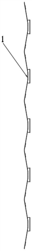
[0041] The fin unit has a plate-shaped main body, and the plate-shaped main body is a curved plate;

[0042] The plate-shaped main body is provided with a tube hole 1 on its protruding top and forms a flanging around the tube hole 1, and the protruding direction of the flanging is the same as that of the curved plate;

[0043] The plate-shaped main body is formed around the tube hole with a first hollow structure 2 divergently extending from the tube hole 1 to the outer periphery;

[0044] The plate-shaped main body is formed with a first diversion groove 5 on one or both sides of the pipe hole along the radial direction of the pipe hole 1. One end of the first diversion groove 5 extends to the edge of the plate-shaped main body, and the other end extends to the flange ;

[0045] Wherein the first hollow structure 2 is distributed on both sides of the firs...

Embodiment 2

[0066] Based on the heat exchanging fins in Embodiment 1, a heat exchanger is provided in this embodiment, and the heat exchanger includes any one of the above heat exchanging fins. The heat exchanging fins are stacked and the copper tubes are passed through the tube holes 1 . The heat exchanger can be used for heat exchange in an air conditioner.

[0067] Furthermore, this embodiment further describes the heat exchanger in combination with the specific structure of the heat exchange fins in Embodiment 1.

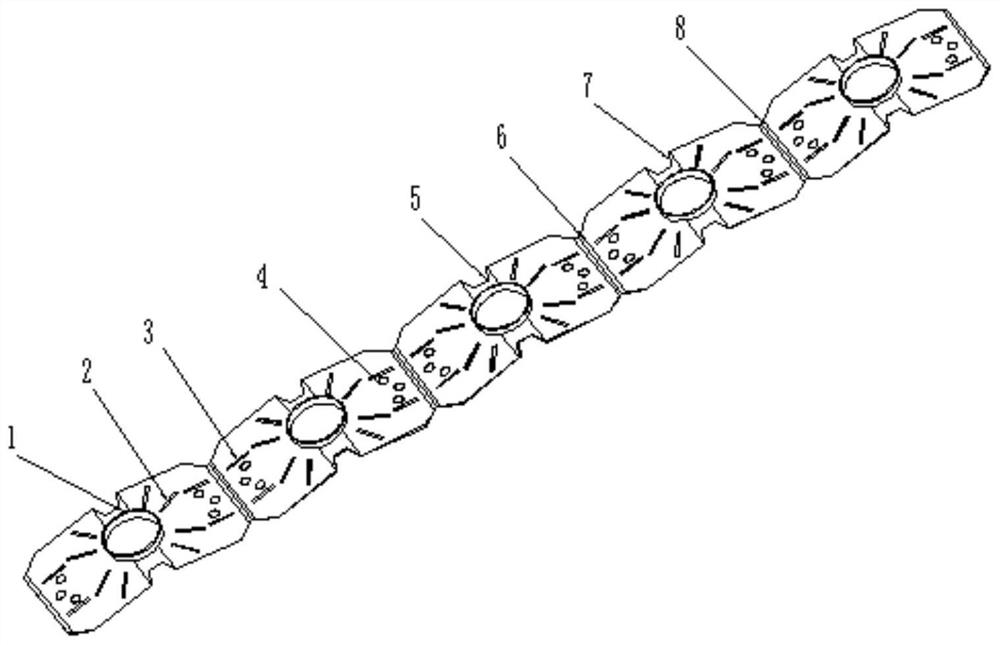
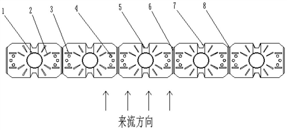
[0068] As shown in 1, the heat exchange fins are formed with tube holes 1, a first hollow structure 2, a second hollow structure 3, protrusions or grooves 4, a first guide groove 5 and a first guide gap 7, a second The diversion groove 6 and the second diversion notch 8 .

[0069] Since the main body of the heat exchange fin used in the heat exchanger is a plate-shaped structure, the first guide groove 5 protrudes toward the direction of the flange of the tube hole ( im...


PUM


Abstract

The invention discloses a heat exchange fin, a heat exchanger and an air conditioner. The heat exchange fin comprises at least one fin unit, each fin unit is provided with a plate-shaped body, and each plate-shaped body is a curved plate. A pipe hole is formed in the convex top of each plate-shaped body, a flange surrounding each pipe hole is formed, and the convex extending direction of each flange is the same as the convex direction of the corresponding plate-shaped body. First hollowed structures extending to the periphery in a divergent manner by taking the corresponding pipe hole as the center are formed at the position, around the corresponding pipe hole, of each plate-shaped body. First flow guide grooves are formed in one side or two sides of the pipe hole in each plate-shaped body in the radial direction of the pipe hole, one end of each first flow guide groove extends to the edge of the corresponding plate-shaped body, and the other end of each first flow guide groove extends to the corresponding flange. The first hollowed structures are distributed on the two sides of the first flow guide grooves.

Description

technical field [0001] The invention relates to the related technical field of air conditioners, in particular to a heat exchange fin, a heat exchanger and an air conditioner. Background technique [0002] At present, the finned tube heat exchanger is the most widely used heat exchanger in the field of refrigeration and air conditioning, and the thermal resistance of this type of heat exchanger is concentrated on the air side outside the tube, which can reach about 70-80% of the total thermal resistance. The heat transfer performance of the side is an important means to improve the capacity of the heat exchanger. At present, finned tube heat exchangers are gradually developing in the direction of miniaturization and compactness, which is specifically reflected in the gradual reduction of the heat exchange tube diameter, but the heat exchange performance of the heat exchanger is also attenuated accordingly. The thinner diameter of the heat exchanger reduces the heat transfer...

Claims


Application Information

Patent Timeline
Patent Type & Authority Applications(China)
IPC IPC(8): F28F1/32F25B39/00
CPCF28F1/325F25B39/00F28F2215/08
Inventor 郭忠玉马腾飞杨瑞琦吕言
Owner GREE ELECTRIC APPLIANCES INC
Why Eureka
Try Eureka