Planetary landing collaborative navigation feature matching method

A collaborative navigation and feature matching technology, applied in the field of deep space exploration, can solve the problems of inability to meet the real-time requirements of landing tasks, sensitivity to illumination changes in landing images, poor matching robustness, etc. The effect of high matching accuracy

Active Publication Date: 2021-09-24
BEIJING INSTITUTE OF TECHNOLOGYGY
View PDF4 Cites 1 Cited by
  • Summary
  • Abstract
  • Description
  • Claims
  • Application Information

AI Technical Summary

Problems solved by technology

However, the SIFT key point extraction has a large amount of calculation, which cannot meet the real-time requirements of the landing mission. In addition, the direction of the SIFT key point depends on the gray level information of the image and is sensitive to the illumination change of the landing image. Poor stickiness

Method used


Image

  • Planetary landing collaborative navigation feature matching method
  • Planetary landing collaborative navigation feature matching method
  • Planetary landing collaborative navigation feature matching method

Examples


Embodiment Construction

[0067] In order to better illustrate the purpose and advantages of the present invention, the content of the invention will be further described below in conjunction with the accompanying drawings and examples.

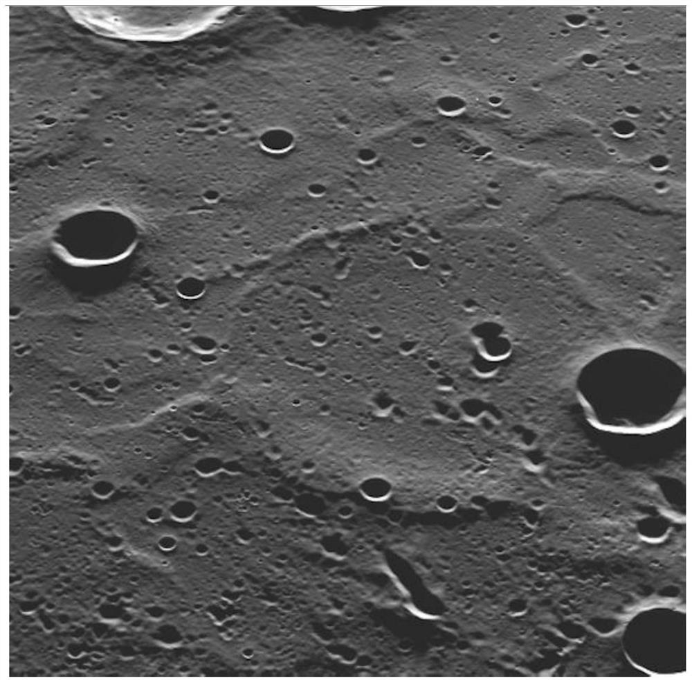
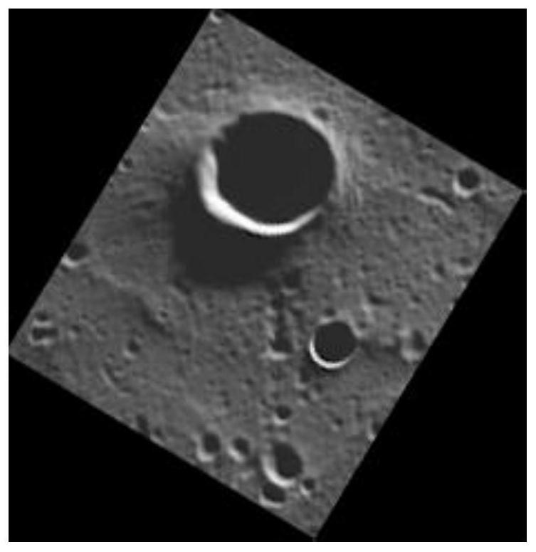
[0068] In order to verify the feasibility of the present invention, based on the actual image of the surface of Mercury taken as the optical image taken by camera A, such as figure 2 , for mathematical simulation verification. use figure 2 The image constructed by affine transformation of part of the image is taken as the optical image taken by camera B, such as image 3 , where the clipped figure 2 Part of the image rotation angle is 31 degrees, the u-direction scaling factor of the image is 0.8, and the v-direction is 1.2.

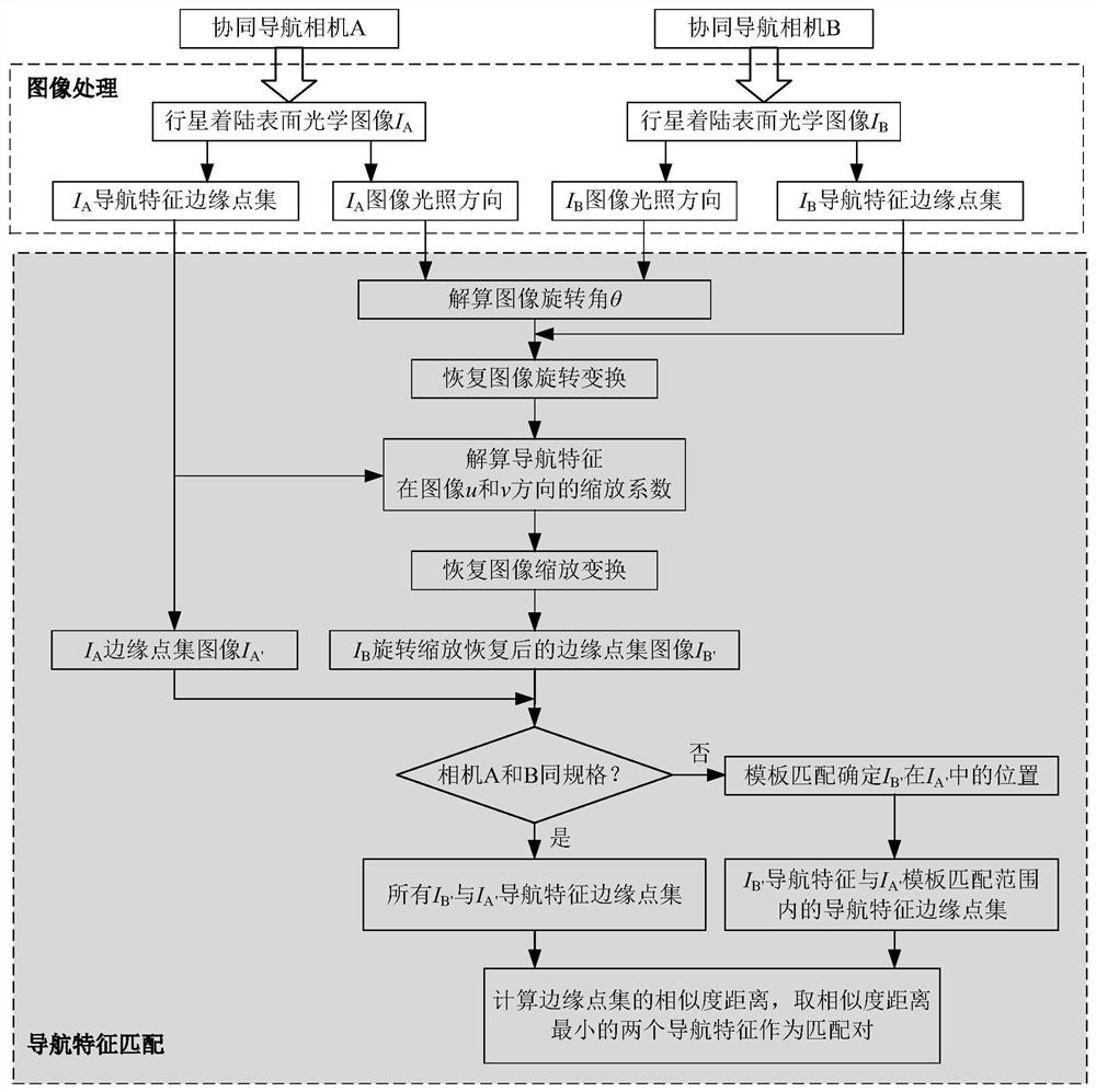
[0069] Such as figure 1 As shown, the specific implementation steps of the planetary landing cooperative navigation feature matching method disclosed in this embodiment are as follows:

[0070] Step 1: The two optical navigation cameras ...


PUM


Abstract

The invention discloses a planetary landing collaborative navigation feature matching method, and belongs to the field of deep space exploration. The implementation method comprises the following steps: enabling a navigation camera A and a navigation camera B for cooperative detection to simultaneously shoot a target area directionally, and respectively detecting a navigation feature edge point set and an illumination direction in an image; calculating a rotation angle between the two images by utilizing the characteristic that the illumination direction of the collaborative navigation image is not changed, and restoring image rotation transformation; on the basis of the detected edge point sets, calculating zoom coefficients of all navigation feature edge point sets PA of the image IA and all navigation feature edge point sets PB'of the rotated image IB in the u and v directions of the image; resolving the zooming coefficients of the two images, and performing zooming recovery on the rotated images; and after rotation and zooming, traversing the similarity distance of the navigation feature edge point sets in the two images to obtain a pair of navigation features with the minimum similarity distance, and calculating a homography matrix T of image transformation by using the global matched navigation feature center point to realize navigation feature matching.

Description

technical field [0001] The invention relates to a characteristic image matching method between cooperative navigation cameras in the process of planetary landing, especially suitable for image matching when optical navigation cameras of deep space probes work cooperatively, and belongs to the field of deep space exploration. Background technique [0002] Planetary landing is one of the most complex tasks for deep space exploration in the future. Cooperative navigation plays an increasingly important role in improving the reliability and success rate of landing missions. Through multi-probe cooperative operations, cooperative navigation can effectively make up for traditional navigation. Observing defects of insufficient information and significantly improving navigation accuracy. Cooperative navigation also brings a series of derivative problems. Among them, the matching of planetary surface features between cooperative navigation cameras has become one of the key technologi...

Claims


Application Information

Patent Timeline
Patent Type & Authority Applications(China)
IPC IPC(8): G06K9/62G06K9/32G06K9/46G06T3/40G06T3/60
CPCG06T3/60G06T3/40
Inventor 朱圣英修义崔平远徐瑞梁子璇葛丹桐
Owner BEIJING INSTITUTE OF TECHNOLOGYGY
Why Eureka
Try Eureka