Starting device and fire extinguishing equipment

A technology of starting device and gas device, which is applied in fire rescue and other directions, can solve the problems of mass casualties and injuries, and achieve the effects of solving the problem of pressure leakage, saving maintenance costs and expanding the scope

Pending Publication Date: 2021-10-01
BEIJING CENTURY LIANBAO NEW FIRE PROTECTION TECH CO LTD +1
View PDF0 Cites 1 Cited by
  • Summary
  • Abstract
  • Description
  • Claims
  • Application Information

AI Technical Summary

Problems solved by technology

If the pressure is released during driving, and the fire cannot be extinguished just in time, it will lead to mass death and injury, and the consequences are very serious

Method used


Image

  • Starting device and fire extinguishing equipment
  • Starting device and fire extinguishing equipment
  • Starting device and fire extinguishing equipment

Examples


Embodiment 1

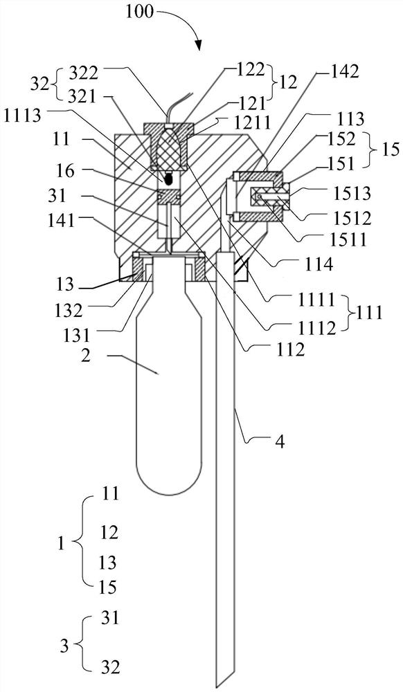
[0052] like figure 1 As shown, one embodiment of the present invention provides a starting device 100. The starting device 100 includes a housing 1, a gas supply device 2, and a trigger device 3.

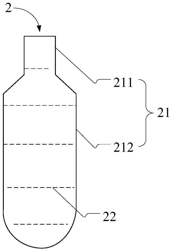
[0053] Specifically, the housing 1 is provided with at least one spout 1513, and the housing 1 is provided with a sealing chamber 1113. like figure 2 As shown, the gas supply device 2 includes an integrated sealing container 21 and a drive medium 22 in the sealing container 21. The sealing container 21 is connected to the housing 1. The initiator 3 is located outside the gas supply device 2. The initiator 3 includes a striker 31 and a trigger 32. The hit needle 31 corresponds to the sealing container 21 for puncture the sealed container 21 to cause the drive medium 22 to discharge the container 21 and form a gas. One end of the initiator 32 is within the sealing chamber 1113, and the other end of the initiator 32 extends through the housing 1 to the casing 1, and the initiator 32 is use...

Embodiment 2

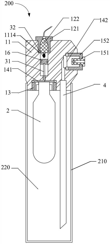
[0130] like Figure 4 Here, another embodiment of the present invention provides a starting device 100 '. The starting device 100 'includes: housing 1', gas supply device 2 ', and initiator 3'.

[0131] Specifically, the housing 1 'is provided with at least one spout 115'. The gas generating device 2 'includes an integrated sealed container 21' and a drive medium 22 'in the sealed container 21'. The sealing container 21 'is connected to the housing 1'. The initiator 3 'is located outside the gas supply device 2'.

[0132] The difference from the foregoing embodiment one is:

[0133] The initiator 3 'includes a striker 31' and a driven 32 '. The striker 31 'corresponds to the sealing container 21' for puncture the sealed container 21 'to cause the drive medium 22' to discharge the sealed container 21 'and form a gas. The initiator 32 'is mounted with the hit needle 31' for driving the striker 31 'to move in a direction near the sealing container 21' to make the collision needle 31 '...


PUM


Abstract

The invention discloses a starting device and fire extinguishing equipment. The starting device comprises a shell, a gas production device and an initiating device; at least one nozzle is formed in the shell, and a sealing cavity is formed in the shell; the gas production device comprises an integrated sealed container and a driving medium sealed in the sealed container, and the sealed container is connected with the shell; the initiating device is located outside the gas generation device and comprises a firing pin and an initiator, and the firing pin corresponds to the sealed container and is used for puncturing the sealed container so that the driving medium can be sprayed out of the sealed container to form gas; one end of the initiator is located in the sealing cavity, and the other end of the initiator penetrates through the shell to extend out of the shell so as to increase the air pressure of the sealing cavity; and the sealing cavity corresponds to the firing pin and is used for directly or indirectly driving the firing pin to move towards the sealed container through the increased air pressure. Thus, a fire extinguishing agent does not need to be stored under pressure, the problem of pressure leakage of existing pressure storage type fire extinguishing equipment is fundamentally solved, the maintenance cost of regular pressurization is saved, and the use reliability of the fire extinguishing equipment is also improved.

Description

Technical field [0001] Technical Field The present invention relates to fire extinguishing apparatus, and more particularly, fire-fighting equipment comprising the device and the activation device relates to a promoter. Background technique [0002] Storage pressure apparatus in order to discharge fire extinguishing agent to the fire, requires a certain amount of filling gas under pressure into the container, the gas pressure is generally in the range 1.2MPa ~ 20MPa. Since the entire apparatus by a fire extinguishing agent storage container, the container valve, pressure gauge, agent discharge port, signal feedback means and many other components, and the long-term storage pressure belt-pressure fire fighting equipment, these components are connected at drain pressure becomes point. Once the leak pressure extinguishing equipment, fire-extinguishing agent can not be normally discharged. Therefore, the storage pressure extinguishing equipment require regular maintenance, filling pr...

Claims


Application Information

Patent Timeline
Patent Type & Authority Applications(China)
IPC IPC(8): A62C13/74A62C13/76
CPCA62C13/74A62C13/76
Inventor 梁荣乔顺平
Owner BEIJING CENTURY LIANBAO NEW FIRE PROTECTION TECH CO LTD
Why Eureka
Try Eureka