Bagged cement loading system

A cement and crane technology, applied in the directions of transportation and packaging, loading/unloading, etc., can solve the problems of reducing the loading efficiency, troubles in the loading process, reducing the vehicle load, etc., so as to improve the loading efficiency and reduce the movement of equipment. The effect of connecting points, reducing equipment failure rate

Pending Publication Date: 2021-10-01
北京宁欣智能科技有限公司
View PDF0 Cites 5 Cited by
  • Summary
  • Abstract
  • Description
  • Claims
  • Application Information

AI Technical Summary

Problems solved by technology

When the vehicle enters the area to be loaded, it is easy to have a position deviation. The structure of the loading head is fixed, and the error cannot be adjusted. It is necessary to repeatedly adjust the vehicle position, which is a waste of time. The vehicle capacity is reduced
[0003] Most of the existing palletizing manipulators run alone on the track, and the relative position relationship with the transmission mechanism is controlled by the automatic program. However, after the shutdown program of the transmission mechanism runs in the actual use process, the transmission mechanism continues to move due to inertia, and the moving distance is about 10mm~ 30mm, this uncertain inertial displacement causes the relative position of the palletizing manipulator and the conveying mechanism to change, the gap between the claw teeth of the palletizing manipulator and the roller platform of the conveying mechanism deviates, and the manipulator cannot be accurately inserted into the gap between the supporting rollers to release the bag The cement is taken away, which brings troubles to the loading process and reduces the loading efficiency

Method used


Image

  • Bagged cement loading system
  • Bagged cement loading system
  • Bagged cement loading system

Examples


Embodiment Construction

[0029] In order to fully understand the purpose, features and effects of the present invention, the present invention will be described in detail through the following specific embodiments, but the present invention is not limited thereto.

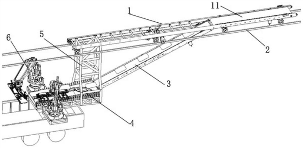
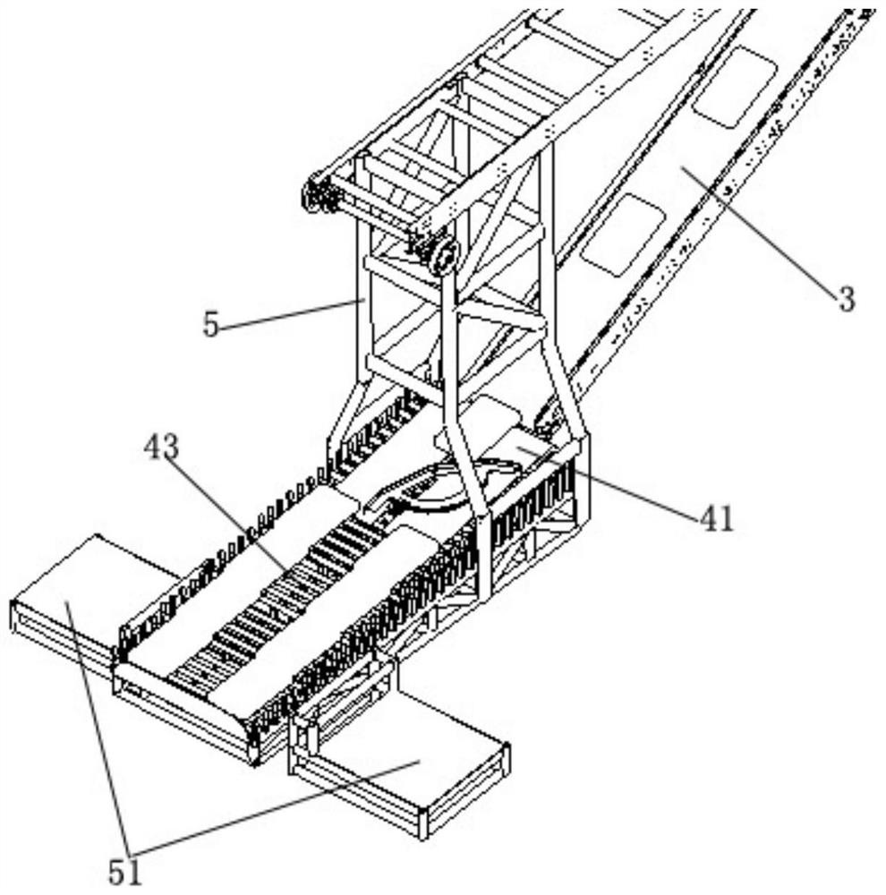
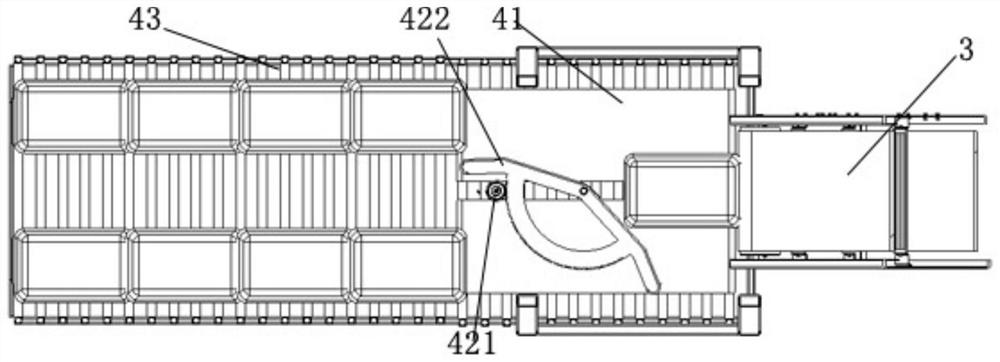
[0030] see figure 1 and figure 2 , A bagged cement loading system provided by the present invention is composed of a conveying crane 1, a track 2, an inclined belt conveyor 3, a subpackaging and stacking device 4, a load-bearing frame 5, and a stacking robot 6. Conveying crane 1 is made up of wheel, vehicle frame and horizontal belt conveyor 11, and wheel is equipped with on the lower end surface of vehicle frame, and wheel rolls on track 2, and track 2 is fixed on the factory building top. The lower side of the left end of the vehicle frame is fixedly connected with the load-bearing frame 5 upper ends, the right end of the vehicle frame is equipped with a horizontal belt conveyor 11, the left end of the horizontal belt conveyor 11 is fi...


PUM


Abstract

The invention discloses a bagged cement loading system, and relates to the technical field of bagged cement loading devices. The bagged cement loading system comprises a track, a conveying crown block, an inclined belt conveyor, a bearing frame, a bag distributing and stacking device and stacking robots. The conveying crown block is in rolling fit with the track, a horizontal belt conveyor is arranged at one end of the conveying crown block and connected with one end of the inclined belt conveyor, the other end of the inclined belt conveyor is connected with the bag distributing and stacking device, the bag distributing and stacking device is fixed to the lower portion of the bearing frame, and the upper portion of the bearing frame is fixedly connected with the other end of the conveying crown block. Base mounting frames are symmetrically fixed to the side faces, on the two sides of the bag distributing and stacking device, of the bearing frame, and the stacking robots are fixed to the base mounting frames. According to the system, the stacking robots are symmetrically fixed to the two sides of a bag stacking mechanism, the relative positions of the stacking robots and the bag stacking mechanism are fixed, it is guaranteed that the stacking robots can accurately grab bags every time, and the loading efficiency is improved.

Description

technical field [0001] The invention relates to the technical field of bagged cement loading devices, in particular to a bagged cement loading system. Background technique [0002] With the enhancement of environmental protection and health awareness and the increase of labor costs, the bagged cement loading device is developing towards automation. At present, the automatic loading devices in the market are mainly divided into two types: the loading head and the palletizing manipulator, both of which transport the bag materials to the waiting station through the transmission mechanism, and then perform palletizing. When the vehicle enters the area to be loaded, it is easy to have a position deviation. The structure of the loading head is fixed, and the error cannot be adjusted. It is necessary to repeatedly adjust the vehicle position, which is a waste of time. The vehicle capacity is reduced. [0003] Most of the existing palletizing manipulators run independently on the ...

Claims


Application Information

Patent Timeline
Patent Type & Authority Applications(China)
IPC IPC(8): B65G67/04B65G67/08
CPCB65G67/04B65G67/08
Inventor 黄荣宁赵欣车金玉郝春燕
Owner 北京宁欣智能科技有限公司
Why Eureka
Try Eureka