Lifting device for construction machinery

A lifting device and construction machinery technology, applied in the direction of lifting devices, lifting frames, cleaning methods using liquids, etc., can solve the problems of increasing the difficulty of internal cleaning, unstable lifting process, and potential safety hazards, and achieve stable lifting, Avoid safety hazards and improve strength

Active Publication Date: 2021-11-19
JIANGSU YUANZHONG MOTOR
View PDF1 Cites 0 Cited by
  • Summary
  • Abstract
  • Description
  • Claims
  • Application Information

AI Technical Summary

Problems solved by technology

[0006] Aiming at the deficiencies of the prior art, the present invention provides a lifting device for construction machinery, which solves the problem of easy slipping after long-term use, making the device a potential safety hazard during use, and impurities are easy to accumulate inside, thereby increasing internal cleanliness. Difficulty, instability during the lifting process, and large shaking problems

Method used


Image

  • Lifting device for construction machinery
  • Lifting device for construction machinery
  • Lifting device for construction machinery

Examples


Embodiment 1

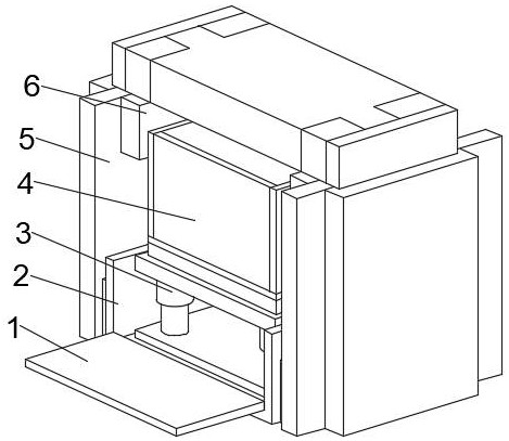
[0040] see Figure 1-6 , the present invention provides a technical solution: a construction machinery lifting device, including a fixed base 2, the bottom of the outer wall on both sides of the fixed base 2 is fixedly connected with a lifting protection frame 5, and the lifting protection frame 5 is close to one side of the fixed base 2 A moving plate 6 is arranged in the middle of the side top, a closing plate 1 is arranged on the front bottom of the fixed base 2, a sliding bracket 3 is fixedly connected to the bottom of the inner cavity of the fixed base 2, and a placement device is arranged on the top of the inner walls of both sides of the sliding bracket 3 4;

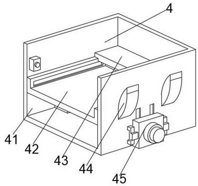
[0041] The placement device 4 includes a placement frame 41, an auxiliary part 42 is fixedly connected to the middle of both sides of the inner wall of the placement frame 41, a cleaning mechanism 43 is provided on the back top of the auxiliary part 42, and an anti-slip mechanism 45 is provided at the middle of th...

Embodiment 2

[0047] see Figure 1-6 , on the basis of Embodiment 1, the present invention provides a technical solution: a method of using a construction machinery lifting device, step 1: install the device, connect the closing plate 1 with the fixed base 2, and fix the The base 2 is connected with the lifting protection frame 5, so that the moving plate 6 moves vertically on the lifting protection frame 5, and the moving plate 6 is connected with the placement device 4;

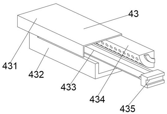
[0048] Step 2: Carry out the intermittent movement of the cleaning mechanism 43 in the horizontal direction through the sliding structure generated by the placing frame 41 and the auxiliary parts 42, connect the buffering inclined block 44 with the placing frame 41, and carry out after the lifting and lowering of the placing frame 41 stops. fixed;

[0049] Step 3: Move the scraper plate 433 by using the movable cavity formed by the protective top cover 431 and the transition box 432, and connect the linkage block 435 wi...


PUM


Abstract

The invention discloses a construction machinery lifting device, which comprises a fixed base, and the bottom of the outer walls on both sides of the fixed base is fixedly connected with a lifting protection frame, and the lifting protection frame is arranged in the middle of the top of one side close to the fixed base. The moving plate, the front bottom of the fixed base is provided with a closing plate, the bottom of the inner cavity of the fixed base is fixedly connected with a sliding bracket, and the top of the inner wall on both sides of the sliding bracket is provided with a placement device. The invention relates to construction machinery technology field. The lifting device for construction machinery makes the lifting of the device more stable. While the placement frame and auxiliary parts form a sliding structure, it can divide the internal space, avoiding the internal impurities affecting the transportation of materials by the device, and the buffering inclined block can increase the contact of the device. The area effectively reduces the shaking amplitude when lifting and lowering, thereby improving the stability of the device, and at the same time clamps and fixes the device when it stops moving, avoiding safety hazards caused by the device slipping.

Description

technical field [0001] The invention relates to the technical field of construction machinery, in particular to a construction machinery lifting device. Background technique [0002] Elevating platform is a kind of hoisting machinery that transports people or objects vertically. It also refers to the equipment for vertical transportation in logistics systems such as factories and automatic warehouses. The lifting platform is often equipped with various plane conveying equipment as different height conveyor lines. The connecting device is generally driven by hydraulic pressure, so it is called hydraulic lifting platform. In addition to being used for cargo transportation at different heights, it is widely used in high-altitude installation, maintenance and other operations. In the field of construction, it is often necessary to work at high altitudes. The risk is relatively high and it is extremely inconvenient, so it is necessary to use an aerial work platform. [0003] Acc...

Claims


Application Information

Patent Timeline
Patent Type & Authority Patents(China)
IPC IPC(8): B66F7/00B66F7/28B08B1/00B08B3/02B08B13/00
CPCB66F7/00B66F7/28B08B1/005B08B3/02B08B13/00
Inventor 许成陶宗跃蔡国明张建新
Owner JIANGSU YUANZHONG MOTOR
Why Eureka
Try Eureka