Protection mechanism for building construction lifting platform based on bidirectional connection
A technology of building construction and two-way connection, which is applied in the direction of building structure, building, building structure support, etc., can solve the problems of increasing the fear of construction workers working at heights, the lifting platform has no protection mechanism, and the moving distance is inaccurate, etc., to achieve Eases fear, improves safety, and facilitates tidying up
- Summary
- Abstract
- Description
- Claims
- Application Information
AI Technical Summary
Problems solved by technology
Method used
Image
Examples
Embodiment 1
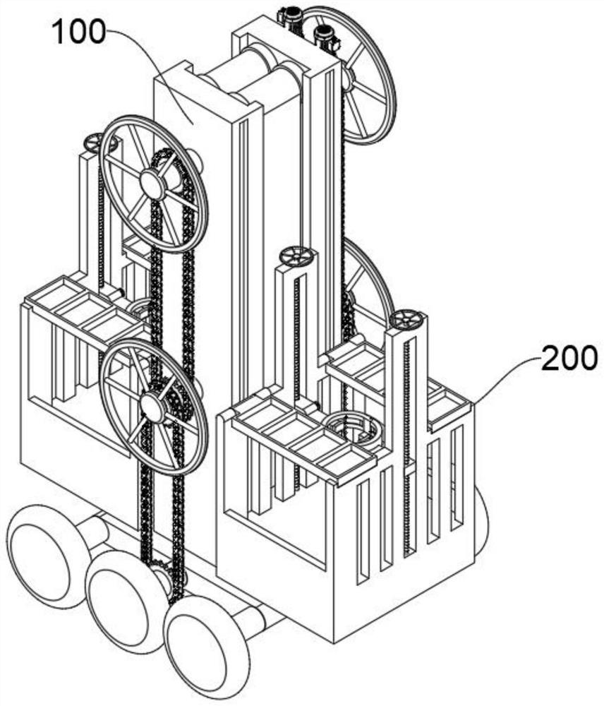
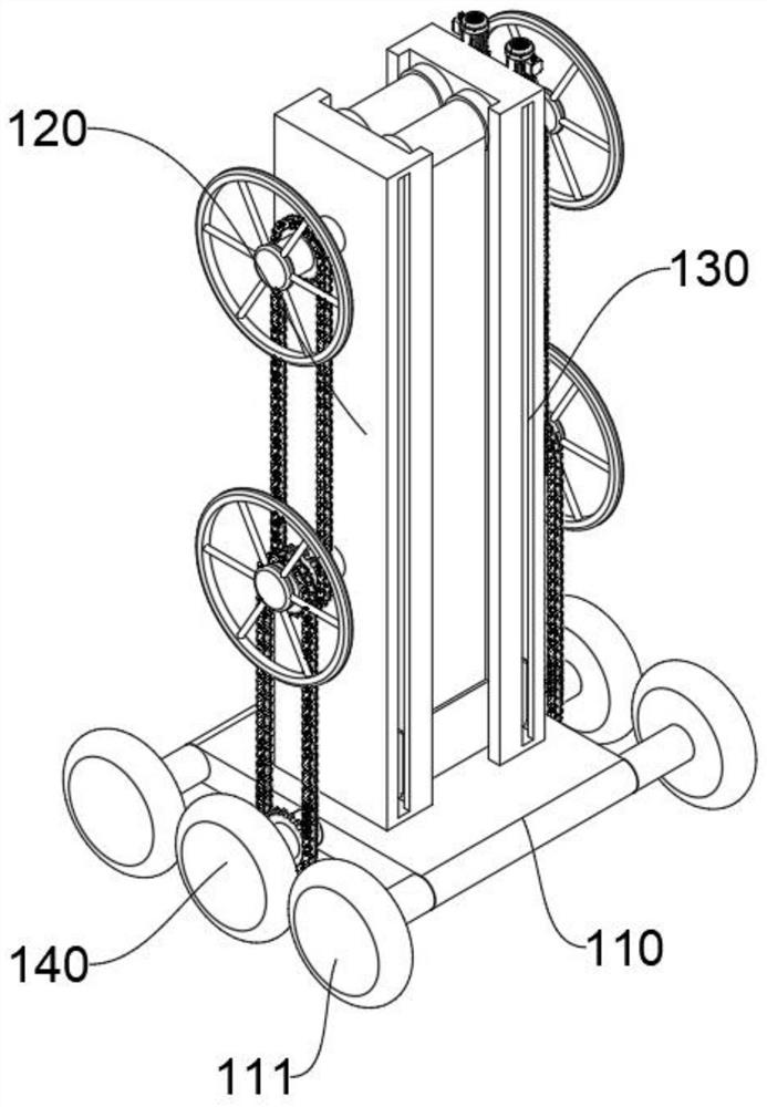
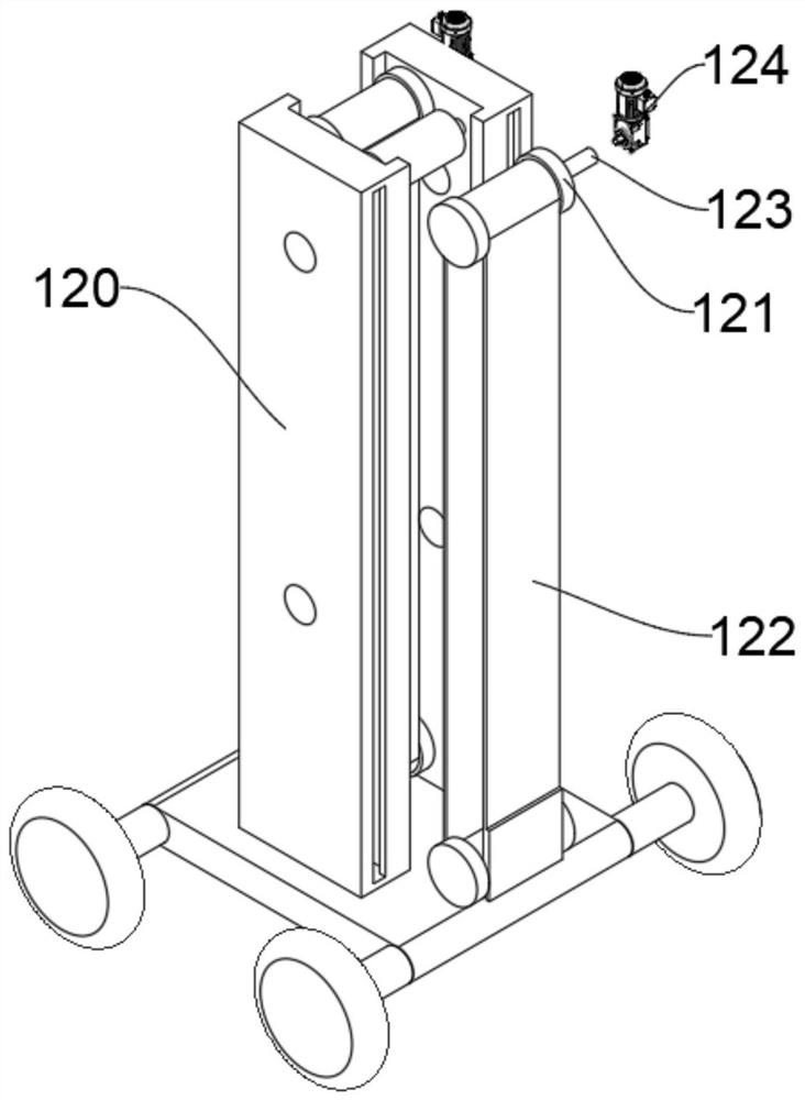
[0039] see Figure 1-Figure 5 As shown, the present embodiment provides a protection mechanism for a building construction lifting platform based on two-way connection, at least including:
[0040]Mobile lifting mechanism 100, mobile lifting mechanism 100 comprises mobile plate 110, and the four corners of the outer wall of mobile plate 110 are provided with universal wheels 111, pushes mobile plate 110, and universal wheel 111 rolls on the ground, is convenient to move, and the center of the top of mobile plate 110 There is a lifting frame 120 at the center of the lifting frame 120, and a conveyor belt 122 is arranged inside the lifting frame 120. Two symmetrical transmission rollers 121 are meshed near the two ends of the conveyor belt 122. The transmission rollers 121 rotate inside the lifting frame 120, and the end of one of the transmission rollers 121 passes The connecting rod 123 is connected with the output shaft of the transmission motor 124, and the outer wall of the...
Embodiment 2
[0046] In order to turn the block 234 against the waist of the construction worker to make the waist limit and fix more stable, the difference between this embodiment and Embodiment 1 is that please refer to Image 6 shown, where:
[0047] The inner wall of the waist fixing plate 230 is provided with a rotary slot 233, and a rotary block 234 slides inside the rotary slot 233, and the rotary block 234 and the rotary slot 233 are in the shape of a "T" that matches, and the end of the rotary block 234 extends out of the rotary slot 233 , it can ensure that the turning block 234 does not break away from the turning groove 233 while sliding. When the construction worker puts the waist inside the waist fixing plate 230, the turning block 234 can be pressed against the waist of the construction worker, so that the waist is more stable and fixed. When the personnel rotates, the end of the rotary block 234 can be driven to rotate inside the rotary groove 233, which is convenient for th...
Embodiment 3
[0050] In order to facilitate the adjustment of the length of the connection belt 225 protruding from the slot 2242, so as to facilitate the movement of construction personnel, the difference between this embodiment and Embodiment 1 is that please refer to Figure 7 shown, where:
[0051] The adjusting plate 224 is provided with a cavity 2241 near the end, and the outer wall of the cavity 2241 is provided with a slot 2242, and the inside of the cavity 2241 is rotated to be provided with a winding rod 2243, and the end of the winding rod 2243 rotates and extends out of the cavity 2241, and Fixedly connected with a transfer handle 2244, the end of the connecting belt 225 is fixedly connected to the outer wall of the winding rod 2243, and the end of the connecting strap 225 slides out of the cavity 2241 from the slot 2242, and the rotating handle 2244 can be held to drive the winding rod 2243 in the cavity 2241 Rotate inside to make the connecting belt 225 wrap around or slide ou...
PUM
 Abstract
Description
Claims
Application Information
 - R&D
- Intellectual Property
- Life Sciences
- Materials
- Tech Scout
- Unparalleled Data Quality
- Higher Quality Content
- 60% Fewer Hallucinations
Browse by: Latest US Patents, China's latest patents, Technical Efficacy Thesaurus, Application Domain, Technology Topic, Popular Technical Reports.
© 2025 PatSnap. All rights reserved.Legal|Privacy policy|Modern Slavery Act Transparency Statement|Sitemap|About US| Contact US: help@patsnap.com


