Camera

A camera and camera technology, applied in the field of cameras, can solve problems such as complex structure, reduce the cost of the whole machine, and large internal space of the camera, and achieve the effect of realizing horizontal rotation and vertical rotation, reducing the cost of the whole machine, and improving control accuracy

Active Publication Date: 2021-10-01
GREE ELECTRIC APPLIANCES INC
View PDF20 Cites 2 Cited by
  • Summary
  • Abstract
  • Description
  • Claims
  • Application Information

AI Technical Summary

Problems solved by technology

[0004] Because a camera needs to be equipped with two motors to realize the horizontal and vertical rotation of the camera, the two motors will occupy a large internal space of the camera, which is not conducive to the miniaturization of the camera; Not conducive to reducing the cost of the whole machine

Method used


Image

  • Camera
  • Camera
  • Camera

Examples


Embodiment 1

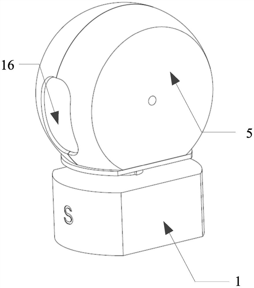
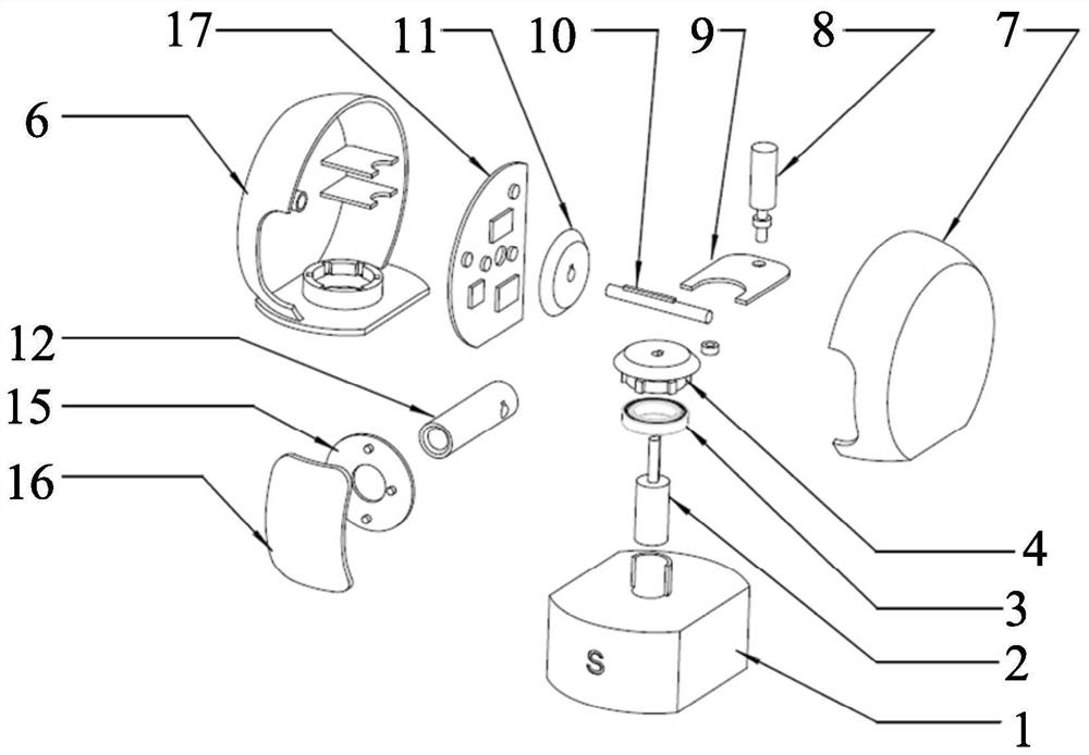
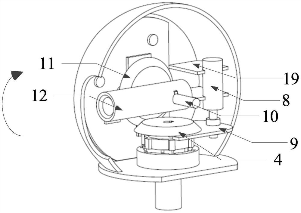
[0074] This embodiment provides a camera, which includes: a driving mechanism for driving the horizontal bevel gear assembly 4 to rotate; and a lifting mechanism 18 for driving the horizontal bevel gear assembly 4 to lift, so that the horizontal bevel gear The component 4 meshes with the vertical bevel gear 11 or structurally engages with the groove 22 of the housing 5 to respectively drive the vertical bevel gear 11 or the housing 5 to rotate, and then realize the vertical rotation or horizontal rotation of the camera 12 .

[0075] The vertical rotation in this embodiment means that the camera head 12 rotates in a vertical plane, and at this time, the camera head 12 rotates with the horizontal axis as the rotation center axis. The horizontal rotation in this embodiment means that the camera head 12 rotates in a horizontal plane, and at this time, the camera head 12 rotates with the vertical axis as the rotation center axis.

[0076] The driving mechanism drives the horizontal...

Embodiment 2

[0084] The main control system 17 is arranged in the first housing 6 , and the main control system 17 is connected with the driving mechanism and the lifting mechanism 18 in communication. The main control system 17 is used to receive user instructions to control the normal and high-efficiency operation of the driving mechanism and the lifting mechanism 18 so as to realize the vertical rotation and horizontal rotation of the camera 12 .

[0085] Specifically, the main control system 17 receives an instruction from the user, and the instruction is an instruction to rotate the camera 12 vertically or an instruction to rotate the camera 12 horizontally.

[0086] Such as Figure 7 As shown, when the command is to rotate the camera 12 vertically, the main control system 17 first sends the first command to control the lifting mechanism 18 to the lifting mechanism 18, and the lifting mechanism 18 immediately executes the first command. At this time, the first command is Command the ...


PUM


Abstract

The invention provides a camera. The camera comprises a driving mechanism and a lifting mechanism, wherein the driving mechanism is used for driving a horizontal oblique bevel gear assembly to rotate; and the lifting mechanism is used for driving the horizontal oblique bevel gear assembly to lift, so that the horizontal oblique bevel gear assembly is meshed with a vertical oblique bevel gear or clamped with a groove structure of a shell to correspondingly drive the vertical oblique bevel gear or the shell to rotate, and then vertical rotation or horizontal rotation of the camera is realized. By using the camera, horizontal and vertical rotation of the camera is controlled by a single motor, and one motor does not occupy a large internal space of the camera, so that miniaturization of the camera is facilitated; and meanwhile, the structure is simple, the control precision is easy to improve, and the cost of the whole machine is reduced.

Description

technical field [0001] The present invention relates to the technical field of photography, in particular to a video camera. Background technique [0002] Home smart cameras can be divided into two categories, one is a rotatable camera and the other is a non-rotatable camera. Rotatable cameras can be divided into three subcategories, including cameras that can be rotated horizontally but not vertically, cameras that can be rotated vertically but not horizontally, and cameras that can be rotated both horizontally and vertically. [0003] Existing cameras with a horizontally and vertically rotatable camera are generally driven by two motors, one motor drives the camera to rotate horizontally, and the other motor drives the camera to rotate vertically. [0004] Because a camera needs to be equipped with two motors to realize the horizontal and vertical rotation of the camera, the two motors will occupy a large internal space of the camera, which is not conducive to the miniatu...

Claims


Application Information

Patent Timeline
Patent Type & Authority Applications(China)
IPC IPC(8): F16M11/08F16M11/10F16M11/18H04N5/225H04N5/232
CPCF16M11/08F16M11/10F16M11/18H04N23/50H04N23/56H04N23/55H04N23/695
Inventor 龙世才邱博文周颖许超谢明
Owner GREE ELECTRIC APPLIANCES INC
Why Eureka
Try Eureka