Highway engineering thickness detection equipment

A technology of thickness detection and engineering, which is applied in the field of thickness detection equipment for highway engineering, can solve problems such as broken cameras, gravel residues are easy to fall and pollute, and affect the clarity of camera shooting, so as to reduce impact deformation damage and ensure shrinkage reset efficiency , the effect of improving clarity and accuracy

Pending Publication Date: 2021-10-01
北京建企动力科技工程有限公司
View PDF1 Cites 2 Cited by
  • Summary
  • Abstract
  • Description
  • Claims
  • Application Information

AI Technical Summary

Problems solved by technology

[0006] In order to make up for the shortcomings of the existing technology, the telescopic mechanism drives the camera to be inserted into the detection hole to take pictures and read the scale data inserted into the detection hole in the prior art, and then compare the scale data with the image information to quickly measure the thickness between different levels of the road information, but there

Method used


Image

  • Highway engineering thickness detection equipment
  • Highway engineering thickness detection equipment
  • Highway engineering thickness detection equipment

Examples


Embodiment 1

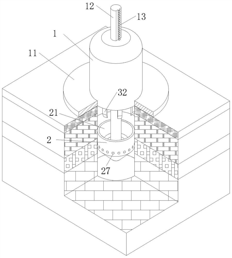
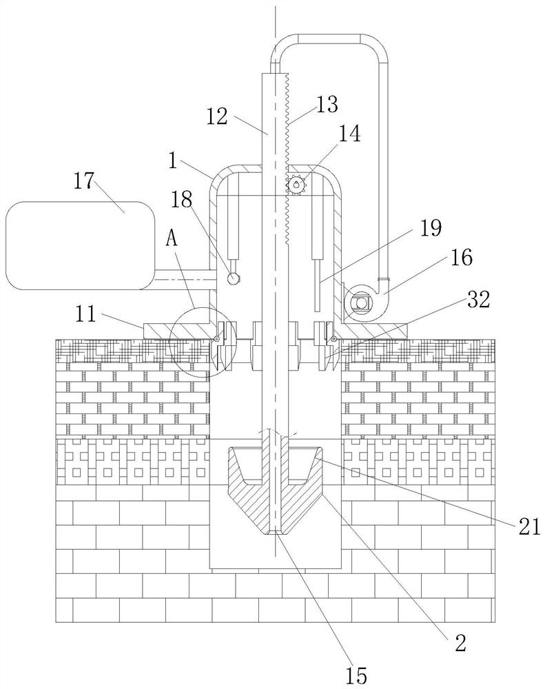
[0029] Such as Figure 1 to Figure 4 As shown, a thickness detection device for highway engineering according to the present invention includes a body 1 and a pressure plate 11; a vertical rod 12 is slidably connected to the body 1, and a rack 13 is provided on one side of the vertical rod 12, and a rack 13 is provided in the body 1 A gear 14 is rotationally connected to the corresponding position of the rack 13, and the gear 14 is driven to rotate by a motor; the pole 12 is provided with a No. 1 hole 15 that runs through the pole 12. The air blower 16 communicates; the side of the body 1 communicates with a dust bag 17 through an exhaust pipe; the body 1 is respectively fixedly connected with a camera 18 and a scale 19 through a pair of symmetrically arranged electric push rods; The telescopic mechanism drives the camera 18 to be inserted into the detection hole to take pictures and read the data of the scale 19 inserted into the detection hole, and then compare the data of t...

Embodiment 2

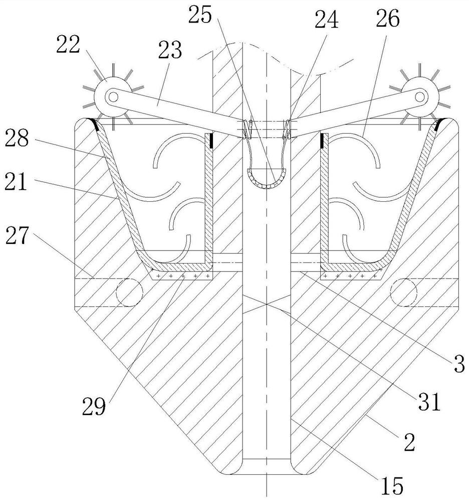
[0038] Such as Figure 5 As shown in Comparative Example 1, another embodiment of the present invention is: the side of the elastic rod 36 close to the elastic ring 38 is slidably connected with a shunt ring 4, the cross section of the shunt ring 4 is herringbone, and the shunt ring 4 There is a sealing groove on the inner periphery, and a damping ring 41 with an inner diameter slightly smaller than the elastic rod 36 is set inside the sealing groove; through the damping ring 41 and the diverter ring 4, the airflow ejected from the elastic ring 38 is evenly dispersed to further improve the compressed air flow rate. Clean up the efficiency of the rotating groove 34.

[0039] A group of C-shaped pieces 42 are evenly distributed on the side of the shunt ring 4 close to the elastic ring 38, and one end of the C-shaped piece 42 near the elastic rod 36 is embedded in the shunt ring 4, and the other end is suspended in the air; the free end of the C-shaped piece 42 The inner side is...


PUM


Abstract

The invention belongs to the technical field of highway detection equipment, and particularly relates to highway engineering thickness detection equipment which comprises a body and a pressing plate. A vertical rod is slidably connected into the body, a rack is arranged on one side of the vertical rod, a gear is rotatably connected to the position, corresponding to the rack, in the body, and the gear is driven by a motor to rotate. A first hole penetrating through the vertical rod is formed in the vertical rod, and the bottom of the first hole communicates with an air blower on the side face of the body through a hose. One side of the body is communicated with a dust collection bag through an exhaust pipe; a camera and a scale are fixedly connected in the body through a pair of symmetrically arranged electric push rods respectively; and before the camera is inserted into the detection hole, compressed air is pumped into the first hole through the air blower, and the detection hole is purged by high-speed airflow, so that residual dust and loose broken stones on the inner wall and the bottom of the detection hole are cleaned, and collision deformation damage to the camera and the scale is reduced.

Description

technical field [0001] The invention belongs to the technical field of road testing equipment, in particular to a thickness testing equipment for highway engineering. Background technique [0002] Highway engineering refers to the survey, measurement, design, construction, maintenance, and management of highway structures. During the construction process of highway engineering, relevant highway engineering supervision needs to detect the paving thickness of various materials on the road. [0003] There are also some technical solutions for highway testing equipment in the prior art. For example, a Chinese patent with application number 202021071640.9 discloses a thickness testing equipment for highway engineering supervision, including a body, the bottom of which is fixed with a measuring plate. Ruler, the side of the measuring ruler is provided with a connecting rod, the bottom end of the connecting rod is fixed with a camera, the outside of the camera is fixed with a light...

Claims


Application Information

Patent Timeline
IPC IPC(8): G01B5/06
CPCG01B5/06
Inventor 赵芮
Owner 北京建企动力科技工程有限公司
Why Eureka
Try Eureka