
Optical waveguide mount

Active Publication Date: 2019-06-27
MICROSOFT TECH LICENSING LLC
View PDF8 Cites 0 Cited by
  • Summary
  • Abstract
  • Description
  • Claims
  • Application Information

AI Technical Summary

Benefits of technology

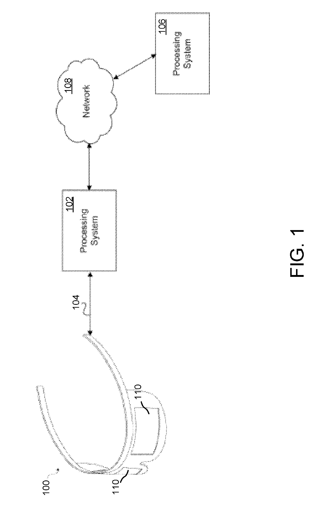
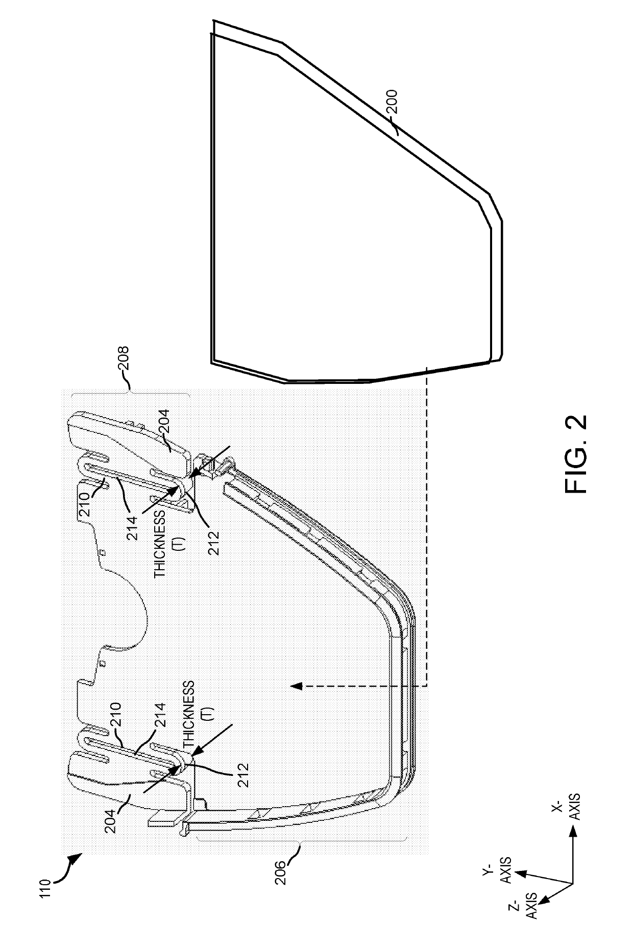
The patent text describes various optical mounts that are designed to be resistant to the stresses that can be experienced by augmented reality-Headmounted Devices (AR-HMDs). The optical mounts have a mechanical compliance and resiliency to absorb and mitigate thermal and mechanical stresses. The techniques improve the clarity and accuracy of images produced by optical devices by providing a mount that absorbs and mitigates thermal and other mechanical stresses. The optical mounts have a compliance joint that allows the mount to have an elasticity or compliance in a first direction, designed to mitigate bowing and warping of the optical waveguide due to stress experienced by the mount and the optical waveguide. The optical mounts make use of the elasticity to improve the clarity and accuracy of images produced by the optical device. The techniques described in the patent text can improve efficiency with respect to computing resources and perform complex tasks, such as facial recognition and object recognition, with reduced resources.

Problems solved by technology

Furthermore, AR-HMD devices may experience mechanical stresses, such as jarring forces that are created when AR-HMD devices are inadvertently dropped.
The various stresses experienced by AR-HMD devices may damage the one or more optical elements implemented by such devices.
For example, stresses experienced by the AR-HMD devices may damage (e.g., bow, warp, etc.) the one or more optical elements incorporated in the AR-HMD devices.

Method used


Image

  • Optical waveguide mount
  • Optical waveguide mount
  • Optical waveguide mount

Examples


example 1

[0056]An optical waveguide mount, comprising: a first body segment to receive and engage an optical waveguide; a first surface and a second surface disposed on the first body segment, the first surface and the second surface to receive and engage the optical waveguide; and at least one compliance joint disposed in the first body segment, the at least one compliance joint disposed between the first surface and the second surface, the at least one compliance joint allowing the first body segment to have an elasticity or compliance in a first direction of the first body segment, the elasticity or compliance designed to mitigate bowing and / or warping of the optical waveguide due to stress experienced by the optical waveguide mount and / or the optical waveguide.

example 2

[0057]The optical waveguide mount according to Example 1, wherein the first surface and the second surface each comprise an adhesive, the adhesives of the first surface and the second surface to fixedly couple the optical waveguide to the first body segment.

example 3

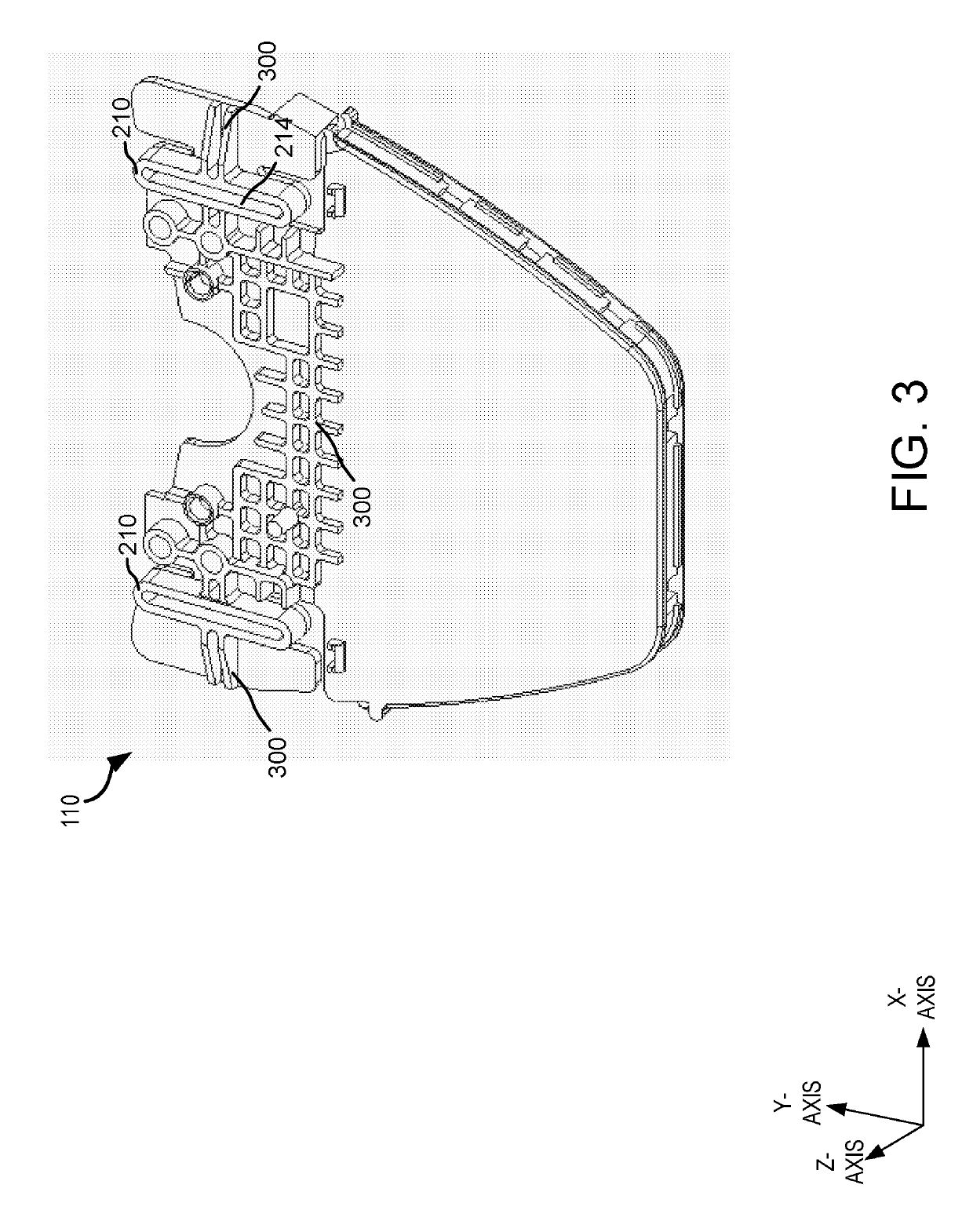
[0058]The optical waveguide mount according to Example 1, wherein the first body segment comprises reinforcing members disposed on a backside of the first body segment, the reinforcing members to mitigate against elasticity or compliance in a second direction of the first body segment, the second direction generally perpendicular to the first direction.


PUM


Abstract

Disclosed optical mounts are resistant to the various stresses that may be experienced by optical display devices. An optical mount is provided with mechanical compliance and resiliency. Such mechanical compliance and resiliency associated with the disclosed optical mounts are intended to absorb thermal and / or mechanical stresses, while protecting and preserving the operational functionality of optical waveguides coupled to the disclosed optical mounts.

Description

BACKGROUND[0001]Virtual reality (VR) and augmented reality (AR) visualization systems are starting to enter the mainstream consumer marketplace, such as in the form of head-mounted display (HMD) devices (“AR-HMD devices”). AR-HMD devices are a promising application of VR and AR technologies.[0002]AR-HMD devices can be embodied in a wearable headset that is arranged to display an image within a short distance from a human eye. Some AR-HMD devices are provided with a frame which has a central portion fitting over a user's (wearer's) nose bridge and left and right support extensions which fit over a user's ears. Optical components are arranged in the frame so as to display an image within a few centimeters of the user's eyes. The image can be a computer-generated image on a display, such as a micro display. The optical components are arranged to transport light of the desired image which is generated on the display to the user's eye to make the image visible to the user. The display on...

Claims


Application Information

Patent Timeline
IPC IPC(8): F21V8/00G02B7/02
CPCG02B6/0093G02B7/02G02B2027/0178G02B27/0176
Inventor TOWERS, CHRISTOPHER ROBERTBOHN, DAVID DOUGLAS
Owner MICROSOFT TECH LICENSING LLC
Learn More