
Synthetic aperture radar (SAR) ship target high-resolution imaging method

An imaging method and high-resolution technology, applied in the field of high-resolution imaging, to achieve the effect of eliminating range unit offset and Doppler frequency offset

Active Publication Date: 2021-10-01
UNIV OF ELECTRONICS SCI & TECH OF CHINA
View PDF5 Cites 4 Cited by
  • Summary
  • Abstract
  • Description
  • Claims
  • Application Information

AI Technical Summary

Problems solved by technology

None of these methods are suitable for ship moving target imaging

Method used


Image

  • Synthetic aperture radar (SAR) ship target high-resolution imaging method
  • Synthetic aperture radar (SAR) ship target high-resolution imaging method
  • Synthetic aperture radar (SAR) ship target high-resolution imaging method

Examples


Embodiment Construction

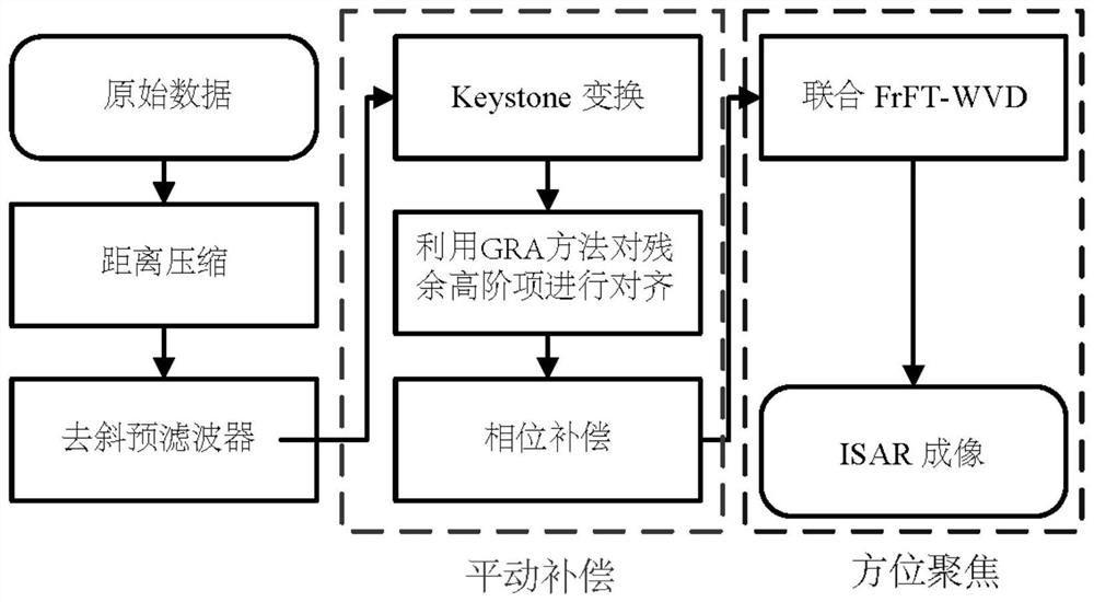
[0026] The present invention mainly adopts the mode of simulation experiment for verification, and the simulation verification platform is MATLAB2020b. The flow chart of the imaging method based on the self-adaptive decomposition of FRFT joint WVD of the present invention is as attached figure 1 As shown, the specific process is as follows:

[0027] Step 1: Establish the SAR spatial geometry structure and complete parameter initialization;

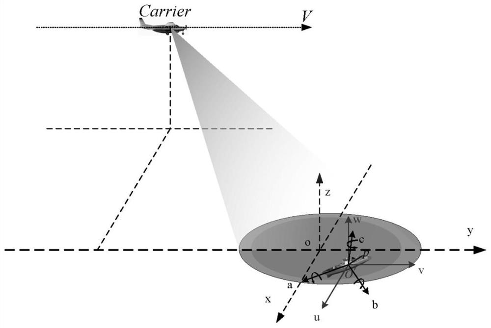
[0028] The SAR geometric structure that the specific example of the present invention adopts is as figure 2 As shown, the system parameter table used is shown in Table 1, where the position coordinates of the carrier aircraft at zero time are (X, Y, H), and the carrier aircraft flies along the Y axis at the speed of V. The ship target is under the power of the engine at a speed of [v x ,v y ,0] T Movement, while doing three-dimensional swings under the action of waves, the swings of the three degrees of freedom are roll, pitch, and y...


PUM


Abstract

The invention discloses a synthetic aperture radar (SAR) ship target high-resolution imaging method, which comprises the following steps of: estimating Doppler ambiguity related parameters, removing Doppler ambiguity of an echo signal and correcting range unit migration through a dechirping pre-filter and Keystone transformation, aligning high-order term migration by using a GRA method, and carrying out imaging processing by using an FrFT combined WVD adaptive decomposition imaging method. According to the method, the problem of SAR image defocusing caused by distance unit deviation and Doppler frequency deviation due to complex motion of a ship target is effectively solved, and the method not only has no cross terms, but also has high resolution.

Description

technical field [0001] The invention belongs to the technical field of radar and relates to high-resolution imaging in synthetic aperture radar moving target detection. Background technique [0002] Synthetic aperture radar (SAR) has been widely used in the fields of automatic guidance and resource detection. With the increasing demand, in addition to high-resolution imaging of ground objects and scenes, it is also necessary to complete focused imaging of moving targets in the scene ( especially surface ship targets). [0003] Due to the non-cooperative nature of the ship's moving target, it will inevitably lead to range cell offset and Doppler frequency offset. Therefore, when a ship moving target appears in the imaging scene, its echo signal tends to spread to multiple range gates. In order to realize the imaging of the ship target, it will face problems such as large range migration, Doppler ambiguity and high phase. And due to the non-stationary three-dimensional swin...

Claims


Application Information

Patent Timeline
Patent Type & Authority Applications(China)
IPC IPC(8): G01S13/90
CPCG01S13/9021G01S13/9029G01S13/9019
Inventor 李中余张晓冬江雨帆杨青孙稚超安洪阳武俊杰杨海光杨建宇
Owner UNIV OF ELECTRONICS SCI & TECH OF CHINA
Learn More