Terahertz radar ultrahigh resolution imaging method

An imaging method, terahertz technology, applied in the field of ultra-high-resolution imaging of terahertz radar, can solve the problems of blurred imaging effect, loss of imaging details, and incomplete solution to sidelobe defocusing, and achieve stable sidelobe defocusing ability , the imaging details are close to complete, and the effect of eliminating the side lobe defocus problem

Active Publication Date: 2020-05-22
UNIV OF ELECTRONICS SCI & TECH OF CHINA
View PDF4 Cites 6 Cited by
  • Summary
  • Abstract
  • Description
  • Claims
  • Application Information

AI Technical Summary

Problems solved by technology

The realization of this technology depends on a certain chance, so the imaging effect is unstable
At the same time, this technology only images sub-apertures with higher energy, but actually loses a lot of imaging details, and cannot achieve ultra-high resolution imaging.
And the sub-aperture energy is used to divide the sub-aperture, and then unifying the sub-aperture width does not set the sub-aperture boundary at the most reasonable position, resulting in this method not completely solving the sidelobe defocus problem of small-aperture sub-aperture division imaging, and the imaging effect is somewhat blurred

Method used


Image

  • Terahertz radar ultrahigh resolution imaging method
  • Terahertz radar ultrahigh resolution imaging method
  • Terahertz radar ultrahigh resolution imaging method

Examples


Embodiment Construction

[0077] The present invention is described in detail below in conjunction with accompanying drawing

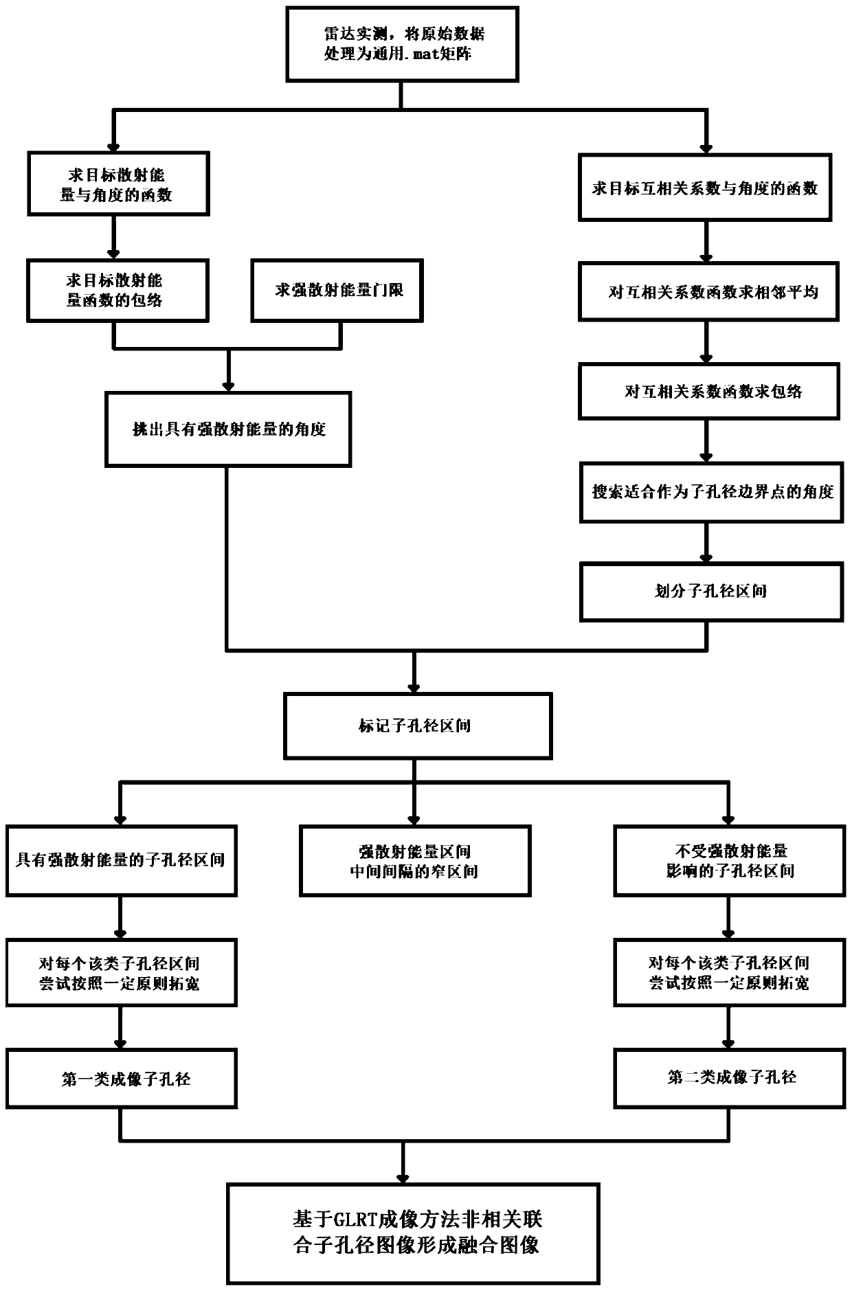
[0078] Refer to attached figure 1 , the specific implementation steps of the present invention are as follows:

[0079] (1) Measured data, the raw data obtained by the radar system is processed into a general .mat matrix file

[0080] After the radar system data is collected, a .dat file is generated for computer processing, and the content of the file is a matrix. The number of rows of the matrix is ​​twice the number of fast time samples, wherein the first half row stores the real part of the fast time echo signal, and the second half row stores the imaginary part of the fast time echo signal. The number of columns in this matrix is ​​the number of slow time samples.

[0081] Process the .dat file: intercept a slow time number corresponding to a circular aperture from the file matrix, and the slow time number M can be calculated according to the angular velocity ω of the r...


PUM


Abstract

The invention belongs to the technical field of radar signal processing, and particularly relates to a terahertz radar ultrahigh resolution imaging method. Terahertz frequency band target scattering energy anisotropy is relatively violent. The common method for imaging the target comprises the step dividing a large aperture into small apertures and jointly imaging sub-aperture images, and the smaller the sub-aperture is, the clearer the details in the small aperture is. The method of the invention is characterized in that in the sub-aperture dividing process, an algorithm based on a sub-aperture cross correlation coefficient in combination with sub-aperture energy is adopted to determine sub-aperture boundaries, and in the sub-aperture dividing method, the technology that the sub-aperturesare sequentially overlapped by a part is adopted. According to the method, the problem of sidelobe defocusing when small-aperture sub-aperture combined imaging is adopted for a scattered energy anisotropic target is better solved. The method solves the problem that when small-aperture sub-aperture combined imaging is adopted for a scattering energy anisotropy target, imaging details are incomplete due to the fact that edge angle scattering energy is cut off by aperture edges.

Description

technical field [0001] The invention belongs to the technical field of radar signal processing, and in particular relates to a terahertz radar ultra-high resolution imaging method. Background technique [0002] For the imaging of targets with anisotropic scattering energy, if the coherent accumulation imaging of wide-aperture data is directly used, the strong scattering energy of the scatterers is only concentrated in a small part of the aperture, which will reduce the signal-to-noise ratio of the target and blur the edges and corners of the target. . The traditional imaging method for imaging targets with anisotropic scattering energy is: divide the wide aperture into multiple sub-apertures with fixed centers and equal widths, and non-correlationally combine these sub-aperture images to form a fusion image based on the GLRT imaging method, and the sub-aperture width The smaller the aperture, the clearer the details. Because terahertz radar has the disadvantage of more int...

Claims


Application Information

Patent Timeline
Patent Type & Authority Applications(China)
IPC IPC(8): G01S13/90G01S7/41
CPCG01S13/90G01S7/41G01S13/9088
Inventor 李晋曾梧桐闵锐皮亦鸣曹宗杰崔宗勇
Owner UNIV OF ELECTRONICS SCI & TECH OF CHINA
Why Eureka
Try Eureka