Self-cleaning water collecting tank for sedimentation tank and control method of self-cleaning water collecting tank

A self-cleaning, water collecting tank technology, applied in the field of water collecting tanks, can solve the problems that the water collecting tank does not have a bottom scraping mechanism, the bottom sediment rolls, and the effect of scraping mud is affected, so as to prevent accumulation, ensure the effect of scraping, and ensure The effect of cleanliness

Inactive Publication Date: 2021-10-08
叶东旭
View PDF0 Cites 2 Cited by
  • Summary
  • Abstract
  • Description
  • Claims
  • Application Information

AI Technical Summary

Problems solved by technology

[0003]Existing sumps generally do not have bottom mud scraping mechanism, and some sumps with this function generally have poor mud scraping effect, and the mud scraping At the same time, it will drive the upper layer of water to flow, causing the bottom sediment to roll, affecting the effect of mud scraping

Method used


Image

  • Self-cleaning water collecting tank for sedimentation tank and control method of self-cleaning water collecting tank
  • Self-cleaning water collecting tank for sedimentation tank and control method of self-cleaning water collecting tank
  • Self-cleaning water collecting tank for sedimentation tank and control method of self-cleaning water collecting tank

Examples


Embodiment 1

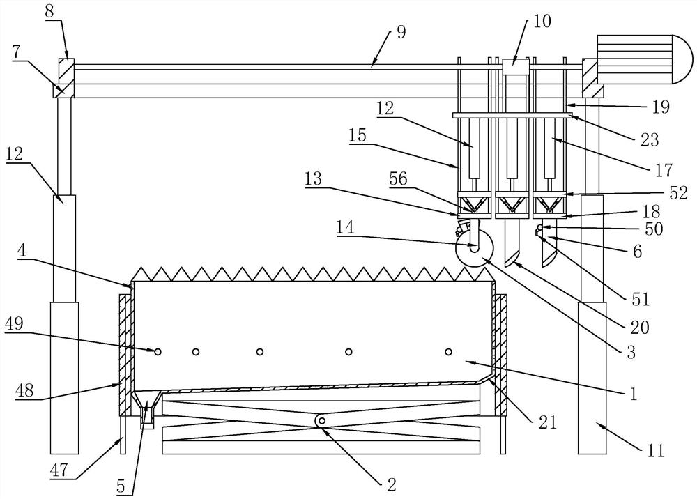
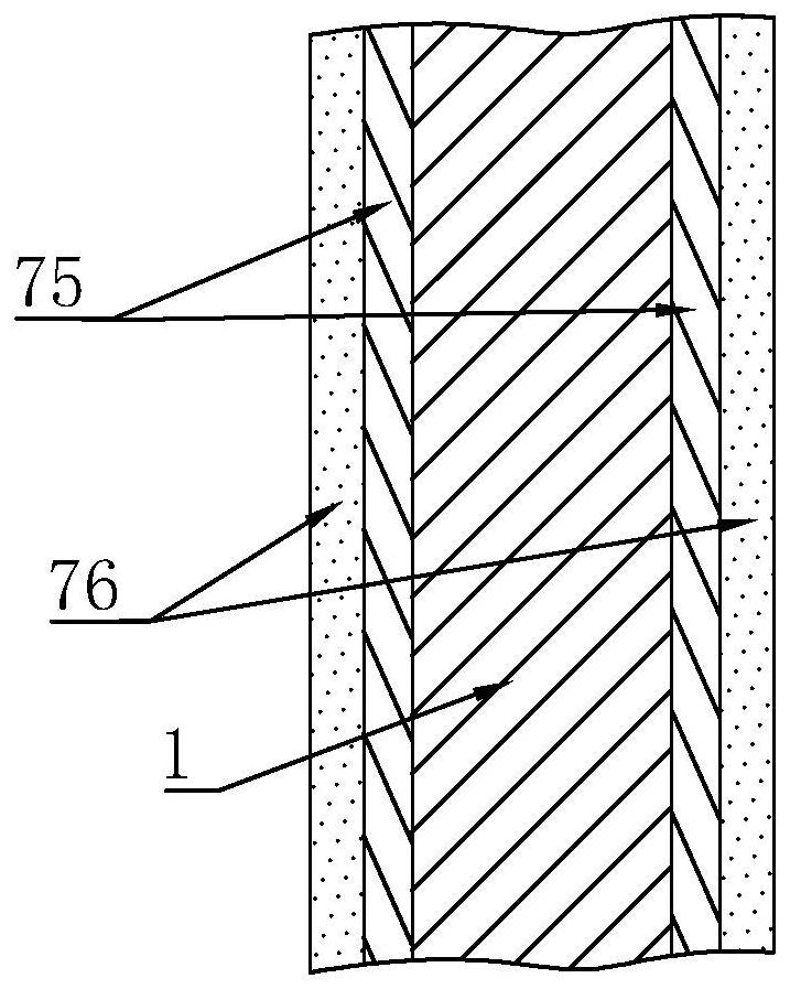
[0090] A self-cleaning sump for a sedimentation tank, comprising a stainless steel tank body 1 and a self-cleaning device, the self-cleaning device comprising

[0091] The tank body lifting mechanism, the tank body lifting mechanism is arranged at the bottom of the stainless steel tank body 1, and is used for raising or lowering the height of the tank body,

[0092] A scrubbing mechanism, the scrubbing mechanism is equipped with a scrubbing lifting assembly and a brush tube 3, which is used to scrub the bottom of the tank body,

[0093] Support mechanism, the support mechanism is erected on the upper end of the stainless steel tank body 1, and is used to place the scrubbing mechanism and related mechanisms;

[0094] The control cabinet is equipped with a control circuit and a controller, which are used to control the work of the electronic components in the stainless steel sink.

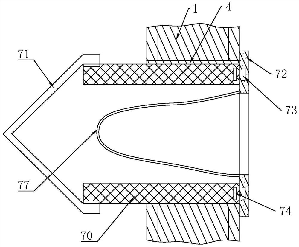
[0095] The upper part of the side wall of one side of the stainless steel tank body 1 is provide...

Embodiment 2

[0117] Further on the basis of Embodiment 1: the brush lifting assembly includes

[0118] Brushing drive cylinder 12, brushing drive cylinder 12 is fixedly arranged on the fixed plate 23, and its drive rod is set downwards,

[0119] Scrub support plate 13, the brush support plate 13 is fixedly connected with the drive rod end of brush drive cylinder 12,

[0120] Scrubbing support frame 14, described scrubbing support frame 14 is arranged on the lower end of scrubbing support plate 13, and brush cylinder 3 rotation is fixed on the grasping and cleaning support frame,

[0121] Scrubbing guide post 15, one end of scrubbing guide post 15 is fixedly connected with scrubbing support plate 13, and the other end is slidably connected with fixed plate 23 up and down,

[0122] A brushing motor, the brushing motor is fixedly arranged on the brushing support plate 13, and drives the brush cylinder 3 to rotate through a transmission belt.

[0123] The brush cylinder 3 is driven to move d...

Embodiment 3

[0125] Further on the basis of embodiment two: the scraping mechanism also includes

[0126] The scraping drive cylinder 17, the brush drive cylinder 12 is fixedly arranged on the fixed plate 23, and its drive rod is set downwards,

[0127] The scraping support plate 18 is fixedly connected to the end of the driving rod of the scraping drive cylinder 17, and the scraper 6 is arranged at the lower end of the scrubbing support plate 13;

[0128] Scraping and washing guide column 19, one end of scraping and washing guide column 19 is fixedly connected with scraping and washing support plate 18, and the other end is slidably connected with fixed plate 23 up and down,

[0129] A soft pad 20, the soft pad 20 is arranged at the lower end of the scraper 6;

[0130] Wherein the brushing mechanism and the scraping mechanism are arranged on the fixed plate 23, the number of the scraping mechanism is two, a gap is formed between the two scraping mechanisms, and the brushing mechanism and...


PUM


Abstract

The invention discloses a self-cleaning water collecting tank for a sedimentation tank. The water collecting tank comprises a stainless steel tank body and a self-cleaning device, the self-cleaning device comprises a tank body lifting mechanism, a brushing mechanism, a supporting mechanism and a control circuit; the tank body lifting mechanism is arranged at the bottom of the stainless steel tank body and is used for increasing or decreasing the height of the tank body, and the brushing mechanism is provided with a brushing lifting assembly and a brushing cylinder for scrubbing the bottom of the tank body; the supporting mechanism is erected at the upper end of the stainless steel tank body and used for placing the scrubbing mechanism; and a control circuit iand a controller are arranged in the external control cabinet, and the control cabinet is used for controlling the electronic components in the cleaning device to work.

Description

technical field [0001] The invention belongs to the technical field of water collection tanks, in particular to a self-cleaning water collection tank for sedimentation tanks and a control method thereof. Background technique [0002] The sump is a device used to uniformly collect the overflowing clean water. It is mainly used at the water outlet of the sedimentation tank, and often adopts a strip hole type or a sawtooth type. A sedimentation tank is a structure that uses sedimentation to remove suspended solids in water, and the sedimentation tank is widely used in wastewater treatment. [0003] Existing sumps generally do not have a mud scraping mechanism at the bottom. Some sumps with this function generally have poor mud scraping effect, and will drive the upper layer of water to flow while scraping mud, causing the bottom mud to roll, affecting the scraping effect. mud effect. Contents of the invention [0004] In view of the deficiencies in the prior art, the object...

Claims


Application Information

Patent Timeline
Patent Type & Authority Applications(China)
IPC IPC(8): B01D21/24B01D21/30B01D21/32B01D21/00B01D21/34B01D21/04B01D36/04B01D35/16
CPCB01D21/2444B01D21/30B01D21/32B01D21/0006B01D21/34B01D21/04B01D21/0012B01D36/04B01D35/16
Inventor 不公告发明人
Owner 叶东旭
Why Eureka
Try Eureka