Trolley for conveying power supply equipment
A technology for power supply equipment and trolleys, which is applied in the direction of trolleys, single-axis trolleys, trolley accessories, etc., and can solve problems such as flying dust, detachment from the trolley, and unstable placement of the trolley to achieve the effect of avoiding unstable placement and superior placement environment
- Summary
- Abstract
- Description
- Claims
- Application Information
AI Technical Summary
Problems solved by technology
Method used
Image
Examples
no. 1 example
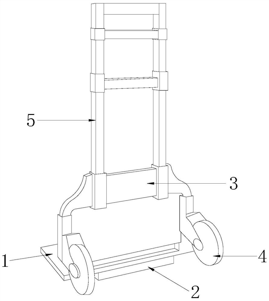
[0028] Such as Figure 1-Figure 4 As shown, the present invention provides a technical solution of a trolley for transporting power equipment:
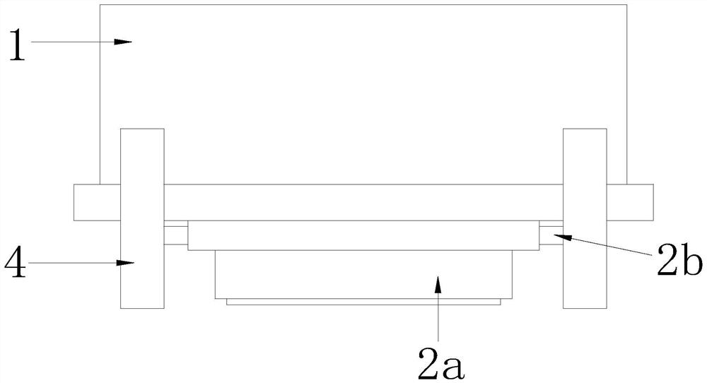
[0029] Such as Figure 1-Figure 3 As shown, a trolley for transporting power equipment, its structure includes a storage board 1, a protective device 2, a backing board 3, a moving wheel 4, and a push-pull rod 5. The protection device 2 is installed on the lower surface of the The board 3 is arranged on the rear side of the upper surface of the storage board 1 and cooperates with each other. The moving wheels 4 are provided with two and are symmetrically installed on both sides of the lower surface of the storage board 1. The push-pull rod 5 is installed on the backing board 3 On the upper surface, the protective device 2 includes a vibration protection structure 2a and a cleaning mechanism 2b. The vibration protection structure 2a is arranged on the lower surface of the storage board 1 and is fastened together. The middle part of th...
no. 2 example
[0039] Such as Figure 2-Figure 5 As shown, the present invention provides a technical solution of a trolley for transporting power equipment:
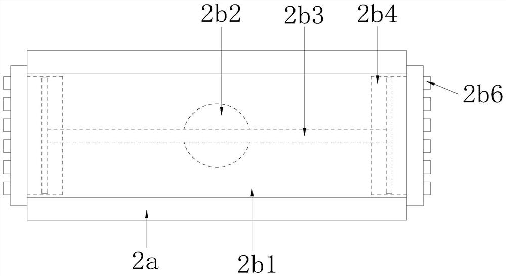
[0040] Such as Figure 2-Figure 4 As shown, a trolley for transporting power equipment, its structure includes that the cleaning mechanism 2b includes a fixed frame 2b1, a push rod 2b2, a movable push plate 2b3, an airbag bar 2b4, an air delivery pipe 2b5, and an air outlet pipe 2b6, and the fixed frame 2b1 It is arranged inside the inner groove 2a2 and cooperates. The end of the push rod 2b2 passes through the lower surface of the fixed frame 2b1 and extends into the perforation provided on the surface of the inner groove 2a2 to connect with the spring ring 2a3. The movable push plate 2b3 It is located inside the fixed frame 2b1 and welded to the top of the push rod 2b2. There are two airbag strips 2b4 which are arranged symmetrically on both sides of the fixed frame 2b1 and on the upper surface of the movable push plate 2b3. The a...
PUM
 Abstract
Description
Claims
Application Information
 - R&D
- Intellectual Property
- Life Sciences
- Materials
- Tech Scout
- Unparalleled Data Quality
- Higher Quality Content
- 60% Fewer Hallucinations
Browse by: Latest US Patents, China's latest patents, Technical Efficacy Thesaurus, Application Domain, Technology Topic, Popular Technical Reports.
© 2025 PatSnap. All rights reserved.Legal|Privacy policy|Modern Slavery Act Transparency Statement|Sitemap|About US| Contact US: help@patsnap.com


