Bridge I-shaped steel

An I-beam and bridge technology, applied in the direction of bridges, bridge construction, bridge materials, etc., can solve the problems of increasing the workload of installers, installation difficulty, and cumbersomeness, so as to reduce installation costs, workload, and offset. effect of chance

Active Publication Date: 2021-10-08
山西中海威轨道交通工程有限公司
View PDF12 Cites 0 Cited by
  • Summary
  • Abstract
  • Description
  • Claims
  • Application Information

AI Technical Summary

Problems solved by technology

[0005] During the operation of existing steel structure bridges, a large number of bolts and connectors are usually used to connect two sets of I-beams, and then play the role of supporting the frame. It is necessary to use connecting members to connect the I-beams fixedly. During the connection process, the bolts need to be inserted into the pre-opened holes and then fixed with bolts. Since the upper and lower ends of the I-beams need to be fixed, and as When the support member is used, it is faced with frequent installation and disassembly. During the installation process, the nut is installed while the bolt is stabilized, which is very cumbersome, which increases the workload of the installer and the difficulty of installation.

Method used


Image

  • Bridge I-shaped steel
  • Bridge I-shaped steel
  • Bridge I-shaped steel

Examples


Embodiment Construction

[0029] The following will clearly and completely describe the technical solutions in the embodiments of the present invention with reference to the accompanying drawings in the embodiments of the present invention. Obviously, the described embodiments are only some, not all, embodiments of the present invention. Based on the embodiments of the present invention, all other embodiments obtained by persons of ordinary skill in the art without making creative efforts belong to the protection scope of the present invention.

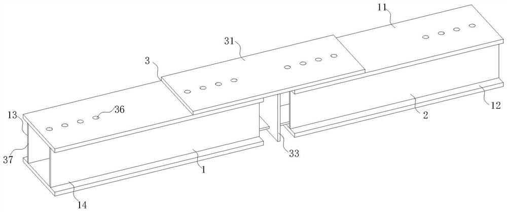
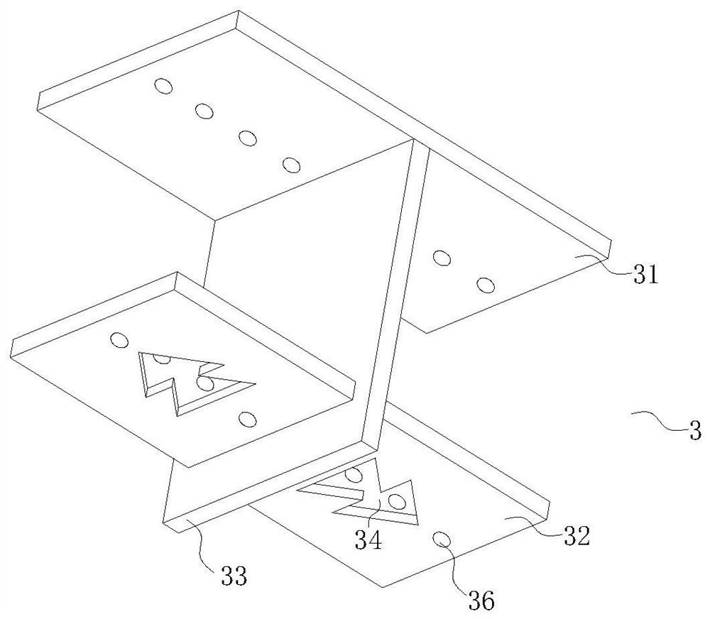
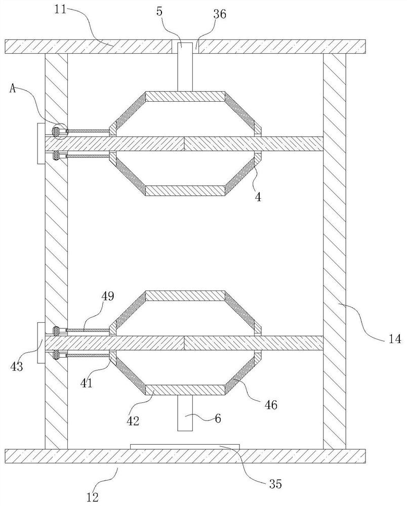
[0030]see Figure 1 to Figure 5 , the present invention provides a technical solution:

[0031] A bridge I-beam, such as Figure 1 to Figure 3 As shown, including I-beam one 1, I-beam two 2 and connection assembly 3, the I-beam one 1 and I-beam two 2 have the same structure, and I-beam one 1 and I-beam two 2 include The upper beam 11, the lower beam 12, and the first intermediate plate 13 and the second intermediate plate 14 arranged parallel to each other b...


PUM


Abstract

The invention relates to the technical field of bridge I-shaped steel, in particular to bridge I-shaped steel which comprises I-shaped steel I, I-shaped steel II and a connecting assembly. The I-shaped steel I and the I-shaped steel II are identical in structure. Each of the I-shaped steel I and the I-shaped steel II comprises an upper beam, a lower beam, a first middle plate and a second middle plate, wherein the first middle plate and the second middle plate are arranged between the upper beam and the lower beam in parallel. Through the arrangement of the connecting assemblies, the positions of the I-shaped steel I and the I-shaped steel II can be quickly calibrated by utilizing the mutual correspondence and matching of the clamping grooves and the clamping blocks, and meanwhile, the stability of the I-shaped steel I and the I-shaped steel II in the mounting process can be effectively improved by utilizing the Christmas tree-shaped cross sections of the clamping blocks, the probability of offset in the installation process of the I-shaped steel I and the I-shaped steel II can be reduced, the installation efficiency can be improved and the installation cost can be reduced. By arranging the first locking mechanism and the second locking mechanism, the multiple sets of first screws and second screws can be connected to the I-shaped steel I, the I-shaped steel I and the connecting assemblies at the same time, and the workload of installation personnel is reduced.

Description

technical field [0001] The invention relates to the technical field of bridge I-beams, in particular to a bridge I-beam. Background technique [0002] Due to the advantages of short construction period and strong adaptability, steel structure bridges have been widely used. I-beams have good bending resistance and are widely used in steel structure bridges. [0003] The existing patent (notification number: CN105371098A) is an I-beam, including an upper beam, a lower beam, and a first middle plate and a second middle plate arranged between the upper beam and the lower beam. Fixed ends are respectively arranged on the opposite surfaces of the beams, and a groove is arranged in the middle of the fixed ends, and the upper and lower ends of the first middle plate and the second middle plate are clamped in the grooves, and the The first middle plate and the second middle plate are provided with through holes arranged at intervals, the through holes on the first middle plate and ...

Claims


Application Information

Patent Timeline
Patent Type & Authority Applications(China)
IPC IPC(8): E01D2/00E01D2/02E01D101/30
CPCE01D2/00E01D2/02E01D2101/30
Inventor 冯志强陈文超
Owner 山西中海威轨道交通工程有限公司
Why Eureka
Try Eureka