Tensiometer system and steel wire rope tension measuring method

A measurement method and tensiometer technology, applied in the field of measurement, can solve problems such as difficult measurement, uneven tension of steel wire ropes, and increased tension, and achieve the effects of improving measurement accuracy, solving inconvenient operation, and convenient measurement

Pending Publication Date: 2021-10-08
NINGBO SPECIAL EQUIP INSPECTION CENT
View PDF11 Cites 2 Cited by
  • Summary
  • Abstract
  • Description
  • Claims
  • Application Information

AI Technical Summary

Problems solved by technology

The DSG type and HD type dynamometers are large in size, and both ends of the steel wire rope need to be supported during measurement, and the force is loaded in the middle, and the elevator wire ropes are arranged closely, resulting in mutual interference between the measuring gauge and the steel wire rope, making it difficult to measure. And it needs to be manually loaded to make the radial tensile displacement of the measured steel wire rope equal, and there is a micro-adjustment, which is time-consuming and the accuracy is not high
The WSG measuring gauge needs to be screwed to fix the sensor on the wire rope, which has the disadvantages of troublesome and time-consuming tooling and difficult control of the radial displacement of the wire rope.
[0005] More importantly, different steel wire ropes will have uneven tension during use. Some steel wire ropes will have greater tension as the length of use increases, making it difficult to be pulled to the same set distance during the measurement process. Measuring tension, the existing electronic products do not provide a targeted solution to this problem, while the traditional measurement method adopts a "one size fits all" approach, no matter whether the tension of the wire rope is tense or not, it is pulled to the same level with great effort. distance to measure the tension at the same distance, it is not humane enough, and it is inconvenient to operate

Method used


Image

  • Tensiometer system and steel wire rope tension measuring method
  • Tensiometer system and steel wire rope tension measuring method
  • Tensiometer system and steel wire rope tension measuring method

Examples


Embodiment Construction

[0046] Embodiments of the present invention are described in detail below, examples of which are shown in the drawings, wherein the same or similar reference numerals designate the same or similar elements or elements having the same or similar functions throughout. The embodiments described below by referring to the figures are exemplary only for explaining the present invention and should not be construed as limiting the present invention.

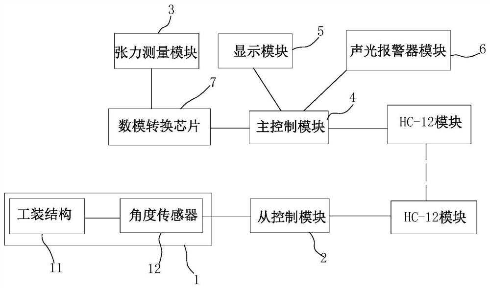
[0047] like Figure 1-12 Shown is a preferred embodiment of the tensiometer system of the present application. As shown in the figure, the tensiometer system includes an angle measurement module 1 for measuring the bending angle caused by deformation during the pulling process of the wire rope, and is connected with the angle measurement module 1 The slave control module 2 for receiving the bending angle information, the tension measurement module 3 for measuring the tension value of the steel wire rope in the pulling process, and the te...


PUM


Abstract

The invention relates to a tensiometer system and a tension measuring method. The system comprises an angle measurement module used for measuring the bending angle generated by deformation in the pulling process of a steel wire rope, a slave control module connected with the angle measurement module to receive bending angle information, a tension measurement module used for measuring the tension value of the steel wire rope in the pulling process, and a master control module; the master control module is respectively connected with the tension measurement module and the slave control module so as to receive the tension value and the bending angle information sent by the slave control module; the master control module is further used for judging the tension value and the bending angle, recording the current tension value when the tension value reaches a set value or the bending angle reaches a preset value, and converting the tension value reaching the set value into the tension value under the condition that the bending angle is the preset value; and whether the tension of the steel wire rope is qualified or not is judged by comparing all tension values under the condition that the bending angle is the preset value with a threshold value. According to the structure and the method, the measurement accuracy and the operation convenience are improved.

Description

technical field [0001] The invention relates to the technical field of measurement, in particular to a tensiometer system and a method for measuring the tension of a steel wire rope. Background technique [0002] The tension of the elevator wire rope is an important factor affecting the comfort and safety of the elevator. At present, there are two main methods for detecting the tension of elevator wire ropes, one is to use a traditional spring dynamometer, and the other is to use an electronic gauge. [0003] The traditional spring dynamometer requires the operator to stand on the top of the car, use the spring dynamometer to pull the steel wire ropes horizontally for the same distance one by one, and then artificially record the tension value of each steel wire rope. This method requires the operator to take into account the two physical quantities of distance and pulling force at the same time, resulting in inconvenient operation, low efficiency, and low measurement accur...

Claims


Application Information

Patent Timeline
Patent Type & Authority Applications(China)
IPC IPC(8): G01L5/10G01L5/102
CPCG01L5/10G01L5/102
Inventor 赵德栋张庆丰
Owner NINGBO SPECIAL EQUIP INSPECTION CENT
Why Eureka
Try Eureka