A device and method for measuring the flow rate of a pressure main pipe of a hydropower station

A technology for pressure main pipe and flow measurement, which is applied in the direction of measuring device, measuring capacity, liquid/fluid solid measurement, etc. It can solve the problems such as no method for determining the diameter of the bypass pipe, no description of the measurement method, and low pressure head. Achieve market application prospects and considerable social benefits, solve the effects of low flow measurement accuracy and reduced straight pipe length

Active Publication Date: 2019-08-06
XIHUA UNIV +1
View PDF6 Cites 0 Cited by
  • Summary
  • Abstract
  • Description
  • Claims
  • Application Information

AI Technical Summary

Problems solved by technology

The application for this invention is to transform the existing flow measurement device, and conduct theoretical derivation in combination with the measurement method, aiming to solve the problem that the on-site circulating water flow cannot be measured online due to large pipe diameter and low pressure head.
[0005] However, the above-mentioned invention application does not provide a method for determining the diameter of the bypass pipe, and cannot be used as a product for standardized production, which lacks practicability; in addition, the k value in the measurement method of the invention application does not indicate that it is a constant, nor does it indicate that It is a constant condition, which will change with the difference of pressure difference. It needs to be measured every time it is used, and the process is relatively complicated, which leads to poor practicability of the whole method

Method used


Image

  • A device and method for measuring the flow rate of a pressure main pipe of a hydropower station
  • A device and method for measuring the flow rate of a pressure main pipe of a hydropower station
  • A device and method for measuring the flow rate of a pressure main pipe of a hydropower station

Examples


Embodiment Construction

[0023] The present invention will be further described below in conjunction with accompanying drawing:

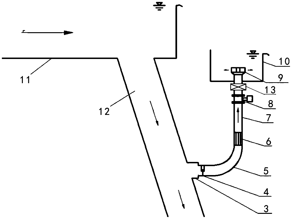
[0024] Such as figure 1 As shown, the device for flow measurement of the pressure main pipe of a hydropower station according to the present invention includes a forebay 11, a pressure main pipe 12, a tee pipe 3, a bypass pipe, a throttle valve 4, a rectifying beam 6, a vortex flowmeter 8, and a valve 13. The overflow window 9 and the overflow tank 10, the pressure main pipe 12 communicates with the forebay 11, and the bypass pipe includes an elbow 5 and a straight pipe 7 connected to each other, and the elbow 5 is connected to the pressure main pipe through the tee pipe 3 12 connected, one end of the throttle valve 4 is connected to the pressure main pipe 12, the other end of the throttle valve 4 is connected to one end of the elbow 5, and the vortex flowmeter 8 used to measure the water flow in the straight pipe 7 is installed in the straight pipe 7, the rectifier bundle...


PUM


Abstract

The invention discloses a measurement device and a measurement method for a hydropower station pressure main tube flow rate, wherein a pressure main tube communicates with a front pool; a bypass tube comprises a bent tube and a straight tube which communicate with each other; the bent tube communicates with and is connected to the pressure main tube by a tee tube; a throttling valve is installed between the tee tube and the bent tube; a flowmeter used to measure the water flow rate in the straight tube is installed on the straight tube; and a water outlet of the straight tube communicates with and is connected to an overflow pool. The invention discloses the measurement method adopted by the device, wherein when a Reynolds number Re of liquid flowing inside the bypass tube is not smaller than 1.3*105, the pressure main tube flow rate will be computed by the formula of DeltaH=K1Q2+K2q2. The measurement device for the hydropower station pressure main tube flow rate disclosed by the invention is characterized in that the Reynolds number of the bypass tube can reach certain conditions through adjustment of the throttling valve, and the flow rate of water in the pressure main tube and the bypass tube will not vary with flow states. In this way, the flow rate of water in the pressure main tube can be computed through measurement of the flow rate of the water inside the bypass tube.

Description

technical field [0001] The invention relates to a flow measuring device for a pressure main pipe of a hydropower station, in particular to a device and a measuring method for measuring the flow of a pressure main pipe of a hydropower station. Background technique [0002] On-line monitoring of turbine efficiency and status in a hydropower station is a means to realize the technical index assessment of the power station, realize economical operation, and save energy and reduce consumption. It will gradually reflect its practicality and significance to the power station. Flow is the main parameter in efficiency measurement, but flow Measurement has become the main cause and bottleneck of this work, which restricts the development of turbine efficiency measurement. [0003] However, in order to be able to measure liquids accurately, a specified straight pipe section must be laid before and after the measuring device. If this condition is not met, obvious errors will occur. The...

Claims


Application Information

Patent Timeline
Patent Type & Authority Patents(China)
IPC IPC(8): G01F1/32G01F15/00
CPCG01F1/32G01F15/00
Inventor 宋占宽曾永忠刘小兵龙驹
Owner XIHUA UNIV
Why Eureka
Try Eureka