Anti-theft power distribution cabinet convenient to maintain
A power distribution cabinet, anti-theft technology, applied in substation/power distribution device housing, electrical components, substation/switch layout details, etc., can solve the problems of lack of mobility, inconvenient installation, disassembly and maintenance of heat dissipation devices, etc., to achieve installation convenient effect
- Summary
- Abstract
- Description
- Claims
- Application Information
AI Technical Summary
Problems solved by technology
Method used
Image

Examples
Embodiment Construction
[0024] The following will clearly and completely describe the technical solutions in the embodiments of the present invention with reference to the accompanying drawings in the embodiments of the present invention. Obviously, the described embodiments are only some, not all, embodiments of the present invention. Based on the embodiments of the present invention, all other embodiments obtained by persons of ordinary skill in the art without making creative efforts belong to the protection scope of the present invention.
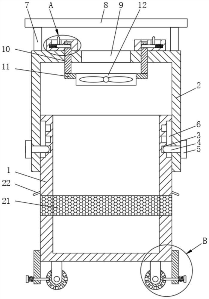
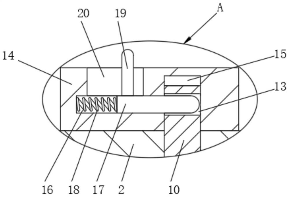
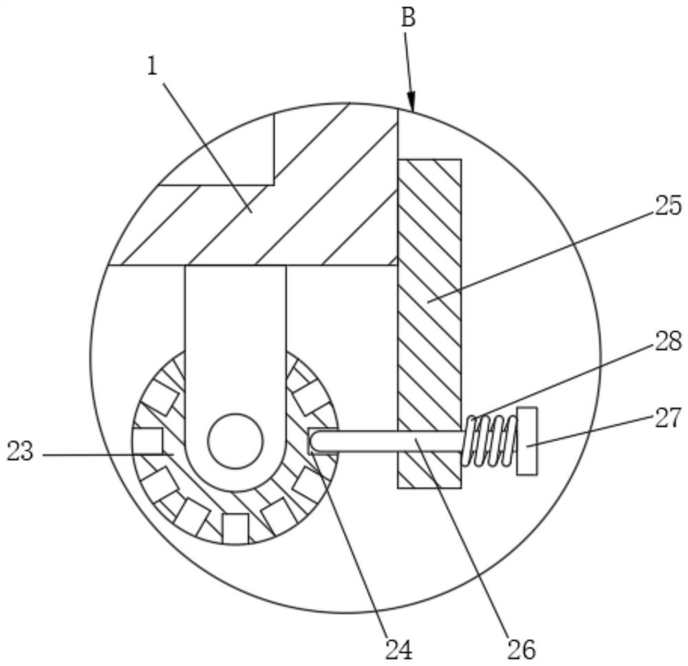
[0025] see Figure 1-5 , an anti-theft power distribution cabinet that is easy to maintain, including a power distribution cabinet body 1, an expansion casing 2 is socketed on the outside of the power distribution cabinet body 1, a threaded hole 3 is opened on the power distribution cabinet body 1, and the expansion casing 2 The interior of the threaded rod 4 is connected with a threaded rod 4, one end of the threaded rod 4 is fixedly connected with a rotary k...
PUM
 Abstract
Description
Claims
Application Information
 - Generate Ideas
- Intellectual Property
- Life Sciences
- Materials
- Tech Scout
- Unparalleled Data Quality
- Higher Quality Content
- 60% Fewer Hallucinations
Browse by: Latest US Patents, China's latest patents, Technical Efficacy Thesaurus, Application Domain, Technology Topic, Popular Technical Reports.
© 2025 PatSnap. All rights reserved.Legal|Privacy policy|Modern Slavery Act Transparency Statement|Sitemap|About US| Contact US: help@patsnap.com