Current sharing control device of DC/DC power supply module

A DC power supply and control device technology, which is applied in the direction of electrical components, support structure installation, and electrical equipment structural parts, etc., can solve problems such as damage to internal circuits, dust ingress, poor device sealing, etc., to achieve less electrical components, energy saving, little effect on stability

Active Publication Date: 2021-10-08
ZHEJIANG DOT LIGHTING
View PDF6 Cites 0 Cited by
  • Summary
  • Abstract
  • Description
  • Claims
  • Application Information

AI Technical Summary

Problems solved by technology

[0004] Aiming at the deficiencies of the prior art, the present invention provides a DC / DC power supply module current sharing control device, which solves the problem that the existing heat dissipation device continuously performs cooling operations on the current sharing controller. When the ambient temperature is low, the current sharing controller When there is less heat generated, there is no need for a cooling device to work, and due to the poor sealing of the device due to the installed cooling device, it is easy to enter dust during storage and damage the internal circuit.

Method used


Image

  • Current sharing control device of DC/DC power supply module
  • Current sharing control device of DC/DC power supply module
  • Current sharing control device of DC/DC power supply module

Examples


Embodiment 1

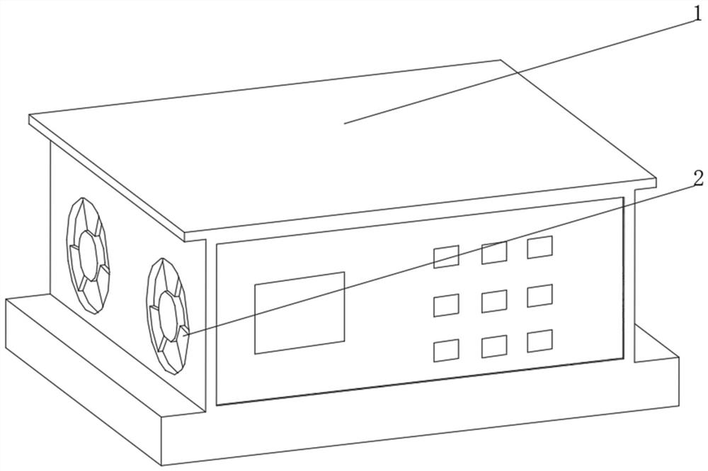
[0037] see Figure 1-3 , the present invention provides a technical solution: a current sharing control device for a DC / DC power module, specifically comprising:

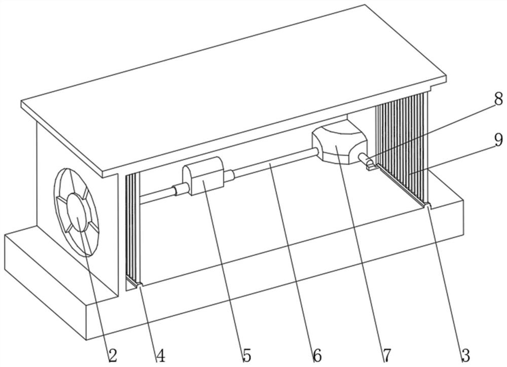
[0038] Control housing 1, a cooling fan 2 is provided on one side of the control housing 1, an air outlet window 3 is provided on the side of the control housing 1 away from the cooling fan 2, and an air inlet window 4 is provided on the side of the inner wall of the control housing 1 close to the cooling fan 2, Both the air outlet window 3 and the air inlet window 4 are provided with an air grid 9;

[0039] The control device 5 is provided with a push rod 6 on both sides of the control device 5, and the side of the push rod 6 away from the control device 5 is connected with a linkage device 7, and the side of the linkage device 7 is provided with a push rod 8, and the push rod 8 is far away from the linkage device One end of 7 is connected with air grid 9;

[0040] Control device 5 comprises:

[0041] Heat colle...

Embodiment 2

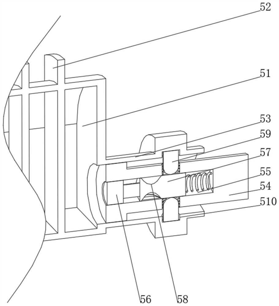
[0044] see Figure 1-4 On the basis of Embodiment 1, the present invention provides a technical solution: the linkage device 7 includes a fixed housing 71, the bottom of the inner wall of the fixed housing 71 is rotatably connected to a turntable 72, and one side of the turntable 72 is respectively provided with a driving seat 73 and a driven seat 74 One side of the driving seat 73 and the driven seat 74 are respectively connected with a driving rod 75 and a driven rod 76 through a rotating connecting rod, a limit buckle 77 is arranged on one side of the rotating disk 72, and a hairpin is arranged between the rotating disk 72 and the bottom of the inner wall of the fixed shell 71. Bar spring 78, the end of drive rod 75 away from drive seat 73 is fixedly connected with push rod 6, the end of driven rod 76 away from follower seat 74 is fixedly connected with push rod 8, and the inside of limit buckle 77 is provided with a main buckle and a secondary buckle And it is fixedly conn...

Embodiment 3

[0047] see Figure 1-5 On the basis of Embodiment 1 and Embodiment 2, the present invention provides a technical solution: the air grid 9 includes a base 91, the inner wall of the base 91 is rotatably connected with a gear 92 through a bearing, and the top of the gear 92 runs through the top of the base 91 and is fixedly connected with a stopper. Plate 93, the two sides of baffle plate 93 are respectively provided with sealing groove 94 and sealing strip 95, gear 92 one side meshes with rack 96, baffle plate 93 tops are rotatably connected with air outlet window 3 and the inner wall top of air inlet window 4, and rack 96 One end is fixedly connected with the push rod 8, and is provided with an air grid 9. When the driven rod 76 moves, it drives the push rod 8 to push the rack 96 to move, and the rack 96 drives the gear 92 to move, and the gear 92 drives the baffle plate 93 to rotate. The air outlet window 3 and the air inlet window 4 are opened. When the device is not in use, ...


PUM


Abstract

The invention discloses a current sharing control device of a DC/DC power supply module. The device specifically comprises a control housing, one side of the control housing is provided with a heat dissipation fan, one side, far away from the heat dissipation fan, of the control housing is provided with an air outlet window, one side, close to the heat dissipation fan, of the inner wall of the control housing is provided with an air inlet window, and the air outlet window and the air inlet window are internally provided with air grids; the two sides of the control device are both provided with ejector rods, the sides, away from the control device, of the ejector rods are connected with a linkage device, one side of the linkage device is provided with a push rod, and the end, away from the linkage device, of the push rod is connected with an air grid. The current sharing control device of the DC/DC power supply module, which relates to the technical field ofcurrent sharing control, can automatically control the start and stop of a heat dissipation device according to the change of a use environment, saves energy, has the stability less affected by environmental factors, has a long service life, is not easy to damage, and has good safety, air tightness and protection performance.

Description

technical field [0001] The invention relates to the technical field of current sharing control, in particular to a current sharing control device of a DC / DC power supply module. Background technique [0002] Since the parameters of each parallel power supply module cannot be completely consistent, if the modules are directly connected in parallel, it is bound to be difficult to ensure that each module will share the load current evenly, which will cause the problem of current imbalance. The main reason for adopting current sharing control is that the main reason why the parallel operation of modules requires current sharing control is because the module The output is a voltage source, and a small deviation in the output voltage will cause a large difference in the output current. The currently used current sharing controllers, especially the current sharing controllers integrated with large equipment, will gradually generate heat during use. The existing heat dissipation de...

Claims


Application Information

Patent Timeline
Patent Type & Authority Applications(China)
IPC IPC(8): H05K5/02H05K5/06H05K7/14H05K7/20
CPCH05K7/20H05K5/06H05K7/20136H05K7/14H05K5/0217
Inventor 董金浩
Owner ZHEJIANG DOT LIGHTING
Why Eureka
Try Eureka