Supercharge Your Innovation With Domain-Expert AI Agents!

Micro-fluidic chip with self-driven unit, micro-fluidic method and application of micro-fluidic chip

A microfluidic chip, self-driven technology, applied in chemical instruments and methods, laboratory containers, laboratory utensils, etc., can solve the problems of complex operation and pollution, and achieve convenient operation, wide application range, simple and comprehensive control effect

Active Publication Date: 2021-10-12
PEKING UNION MEDICAL COLLEGE HOSPITAL CHINESE ACAD OF MEDICAL SCI +1
View PDF5 Cites 0 Cited by
  • Summary
  • Abstract
  • Description
  • Claims
  • Application Information

AI Technical Summary

Problems solved by technology

However, since the detection of biochemistry, immunity and nucleic acid needs to involve multi-step fluid operation reactions, transferring them to microfluidic chips requires complex fluid operations such as mu

Method used


Image

  • Micro-fluidic chip with self-driven unit, micro-fluidic method and application of micro-fluidic chip
  • Micro-fluidic chip with self-driven unit, micro-fluidic method and application of micro-fluidic chip
  • Micro-fluidic chip with self-driven unit, micro-fluidic method and application of micro-fluidic chip

Examples


specific experiment example 1

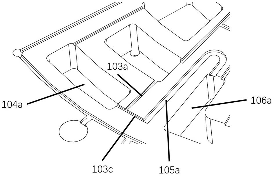
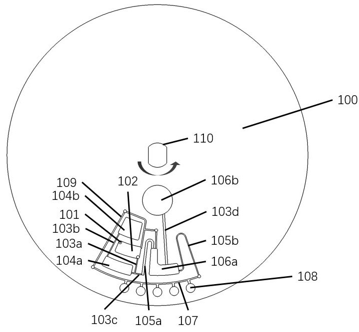
[0124] Sample inlet 101, sample pool 102, first connecting pipe 103a, transfer pool 104a, second connecting pipe 103b, air pool 104b, third connecting pipe 103c, first siphon pipe 105a, mixing pool 106a, aluminum foil liquid bag 106b , the fourth transfer pipe 103d, the second siphon pipe 105b, the distribution pipe 107, the reaction hole 108, the ventilation pipe 109, such as figure 1 As shown, in order to facilitate the distinction of each unit, in this experiment example, the structures of the same unit or type are distinguished by different numbers for the convenience of review.

[0125] In this experimental example, the microfluidic chip is used to realize the biological reaction of two-step constant temperature amplification, and the specific process is as follows.

[0126] Before the start of the experiment, the aluminum foil sac 106b in the microfluidic chip has been pre-filled with diluent and sealed by aluminum foil; the freeze-dried reagent for the first step of con...

specific experiment example 2

[0128] In this experimental example, the microfluidic chip was used to realize a multi-indicator biochemical reaction, and the specific process is as follows.

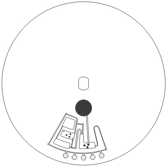
[0129] Before the start of the experiment, the aluminum foil sac 106b in the microfluidic chip has been pre-filled with diluent and sealed by aluminum foil; substrates of different biochemical reactions are fixed in the reaction well 108, such as Figure 3a shown. After the experiment started, the blood was added into the sample pool 102 through the sample port 101, such as Figure 3b shown. Afterwards, the chip undergoes high-speed centrifugation so that the blood enters the transfer pool 104a from the sample pool 102 through the first connecting pipe 103a. At this time, the serum and blood cells are separated under high-speed centrifugation, and the air in the transfer pool 104a is compressed at the same time, so that some Air enters through the second connecting pipe 103b and is stored in the air pool 104b, as F...


PUM


Abstract

The invention relates to a micro-fluidic chip with a self-driven unit, a micro-fluidic method and application of the micro-fluidic chip, and belongs to the technical field of micro-fluidic chips. The micro-fluidic chip with the self-driven unit comprises a reaction cavity, the self-driven unit and a fluid pipeline, a plurality of reaction cavities are arranged along the upstream, the midstream and the downstream in the fluid flowing direction; the self-driven unit can be communicated with the midstream reaction cavity through a fluid pipeline, and the self-driven unit is positioned at the upstream of the upstream reaction cavity; the upstream reaction cavity can be communicated with the midstream reaction cavity through a fluid pipeline; the midstream reaction cavity can be communicated with the downstream reaction cavity through a fluid pipeline; a quantitative shunting mechanism is arranged on the midstream reaction cavity; and compressed air can be generated in theself-driven unit. The micro-fluidic chip and the micro-fluidic method thereof can be suitable for detection experiments in various biological or other fields, are convenient to operate, are simple and easy to implement, and are wide in application range.

Description

technical field [0001] The invention relates to the technical field of microfluidic chips, and more specifically, to a microfluidic chip with a self-driving unit, a microfluidic method and an application thereof. Background technique [0002] Microfluidic chip technology is a technology that integrates the basic operations of sample preparation, separation, reaction and detection in various biological, chemical or medical analysis processes on chips ranging from a few square centimeters to tens of square centimeters. With the characteristics of integration, automation, and small consumption of samples and reagents, it has been widely used in biochemical detection, nucleic acid analysis, immune detection, cell sorting, environmental detection and food safety and other fields. However, since the detection of biochemistry, immunity and nucleic acid needs to involve multi-step fluid operation reactions, transferring them to microfluidic chips requires complex fluid operations su...

Claims


Application Information

Patent Timeline
IPC IPC(8): B01L3/00
CPCB01L3/5027
Inventor 杨启文潘良斌邵昊英殷双
Owner PEKING UNION MEDICAL COLLEGE HOSPITAL CHINESE ACAD OF MEDICAL SCI
Features
  • R&D
  • Intellectual Property
  • Life Sciences
  • Materials
  • Tech Scout
  • Unparalleled Data Quality
  • Higher Quality Content
  • 60% Fewer Hallucinations
Learn More