Double-screen rotating shaft structure

A technology of rotating shaft structure and moving shaft, which is applied in the direction of electrical components, casings/cabinets/drawer components, electrical equipment casings/cabinets/drawers, etc., which can solve the problem of increasing area and occupying space, which is not conducive to product refinement and lightness changes, inability to rely on each other and other issues

Active Publication Date: 2021-10-12
FIRST DOME +1
View PDF14 Cites 0 Cited by
  • Summary
  • Abstract
  • Description
  • Claims
  • Application Information

AI Technical Summary

Problems solved by technology

[0003]However, the above-mentioned structural design, in the process of pivoting, the distance between the two movable parts (the upper cover display end and the host system end) All remain fixed; therefore, when the two movable parts (the display end of the upper cover and the host system end) have a larger thickness respectively, a wider distance must be reserved between the first axis and the second axis, otherwise The two movable parts (the display end of the upper cover and the host system end) will interfere with each other when they are folded, so that the larger distance between the first axis and the second axis will increase the distance between the two moving parts. The expanded area and occupied space of the above two moving parts (the upper cover display end and the host system end) are not conducive to the refinement and lightness of the product

Method used


Image

  • Double-screen rotating shaft structure
  • Double-screen rotating shaft structure
  • Double-screen rotating shaft structure

Examples


Embodiment Construction

[0066] The technical solution of the present invention will be clearly and completely described below, obviously, the described embodiments are part of the embodiments of the present invention, rather than all the embodiments. Based on the embodiments of the present invention, all other embodiments obtained by persons of ordinary skill in the art without making creative efforts belong to the protection scope of the present invention.

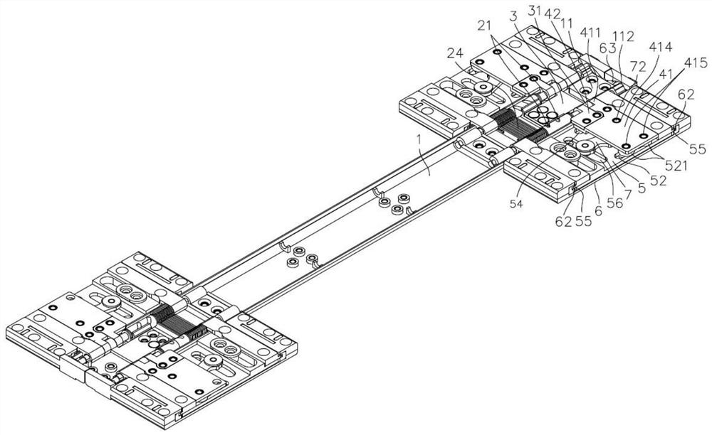
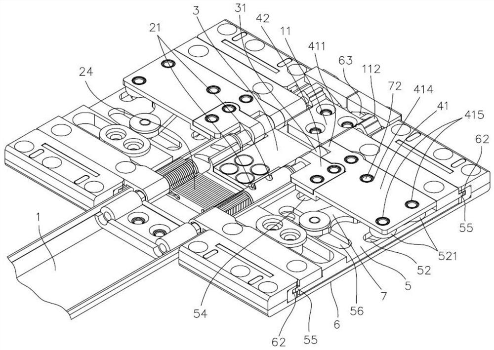
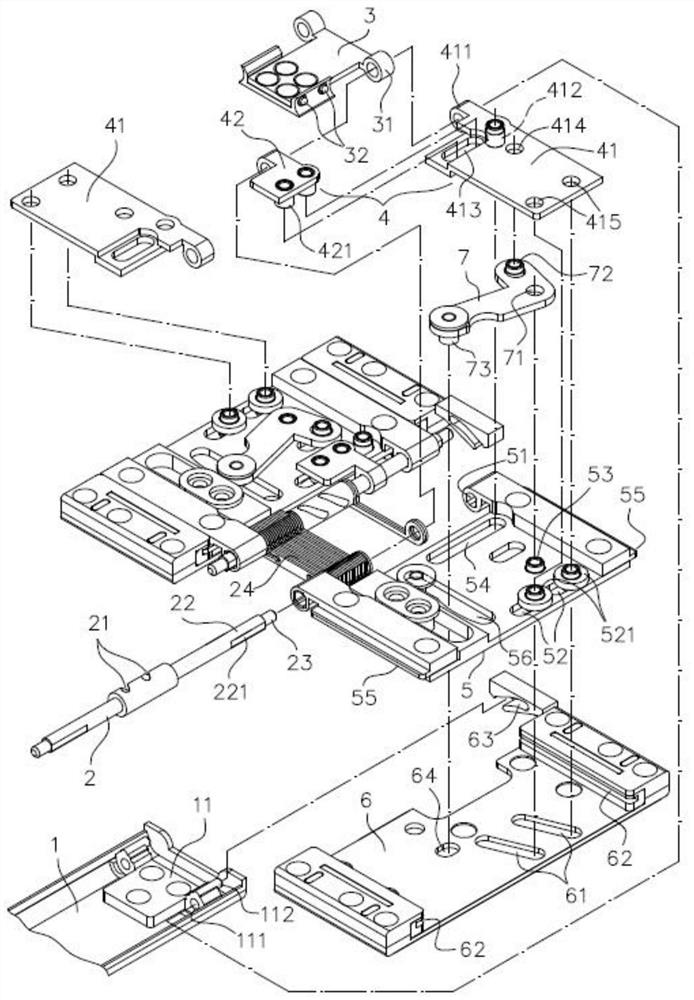
[0067] Such as Figures 1 to 3 As shown, it can be seen that the structure of the present invention includes: a base 1, a linkage shaft 2, a synchronization component 3, a linkage component 4, a connecting piece 5, a sliding piece 6 and a connecting rod 7; wherein the base 1 can be elongated The sheet-like structure is provided with a limiting member 11 at its two ends respectively, and two sides of the limiting member 11 are respectively provided with a shaft hole 111 and a protruding post 112 .

[0068] The limit torsion member 24 is arranged...


PUM


Abstract

A double-screen rotating shaft structure is characterized in that linkage shafts are assembled on the two sides of a base, symmetrical spiral grooves are formed in the surfaces of the two linkage shafts, two protruding points are arranged on a synchronous assembly and embedded into the two spiral grooves respectively, connecting pieces are combined and fixed to the two linkage shafts respectively, and transverse groove holes perpendicular to the linkage shafts are formed in the two connecting pieces respectively. The two linkage shafts are respectively provided with a linkage assembly which moves synchronously with the synchronous assembly in a pivoted mode, two sliding pieces attached to the lower portion of the connecting piece are respectively provided with a chute hole, a guide sliding connecting piece connected to the linkage piece is arranged in each chute hole, the two connecting rods are respectively arranged on the connecting piece in a pivoted mode through the middle portions, and the driving ends of the connecting rods are connected to the linkage assemblies in a pivoted mode. In addition, the driven ends penetrate through the transverse groove holes to drive the sliding pieces, the two connecting pieces abut against each other to drive the linkage shaft to pivot, the linkage assembly is driven by the synchronous assembly along the linkage shaft to drive the connecting rod to pivot, and then the two sliding pieces are linked to move in the direction away from the two linkage shafts respectively.

Description

technical field [0001] The present invention relates to a double-screen rotating shaft structure, especially a rotating shaft structure that enables two movable components to have a minimum distance when they are unfolded or collapsed. Background technique [0002] Traditionally applied to the pivot structure of two movable components (mostly a display screen and a host computer, or two partial display screens that can be connected to each other) in an electronic device, most of the two-axis synchronous actions are designed to make the two movable components (display The screen and the host, or two partial display screens) can be positioned at various opening angles to facilitate the user's operation; The structure of the wrapping pivot device mainly includes: a first shaft and a second shaft, the first shaft and the second shaft are respectively assembled with fixed pieces at one end, and the fixed pieces are respectively combined and fixed on the upper cover of the electro...

Claims


Application Information

Patent Timeline
Patent Type & Authority Applications(China)
IPC IPC(8): H05K5/02
CPCH05K5/0217
Inventor 徐安赐成艳姣
Owner FIRST DOME
Why Eureka
Try Eureka