

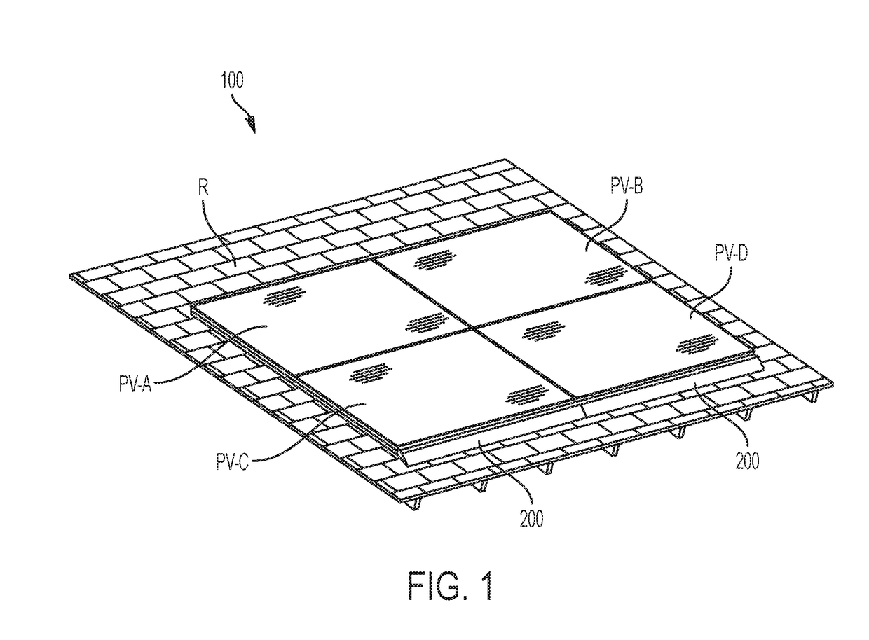
Photovoltaic array skirt and mounting hardware
a technology for photovoltaic arrays and mounting hardware, which is applied in the direction of photovoltaic supports, heat collector mounting/supports, light and heating apparatus, etc., can solve the problems of time-consuming and laborious, and achieve the effect of minimal separation distan
- Summary
- Abstract
- Description
- Claims
- Application Information
AI Technical Summary
Benefits of technology
Problems solved by technology
Method used
Image

Examples
first embodiment
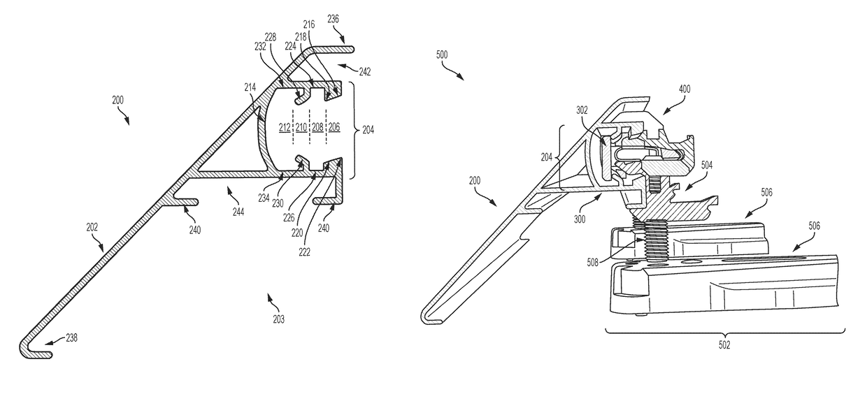
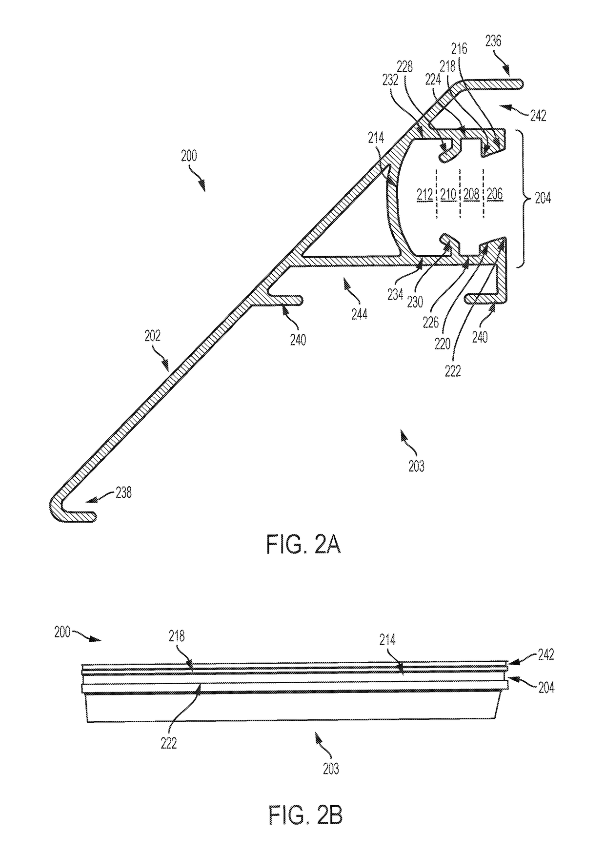
[0069]FIGS. 4A-4H are several views of anti-rotation clip 400. Specifically: FIG. 4A is a top-front perspective view of anti-rotation clip 400; FIG. 4B is a back-bottom perspective view of anti-rotation clip 400; FIG. 4C is a top plan view of anti-rotation clip 400; FIG. 4D is a bottom plan view of anti-rotation clip 400; FIG. 4E is a front profile view of anti-rotation clip 400; FIG. 4F is a left-side profile view of anti-rotation clip 400; FIG. 4G is a back profile view of anti-rotation clip 400; and FIG. 4H is a right-side profile view of anti-rotation clip 400. Anti-rotation clip 400 can be used in a wedging or jamming position in combination with array skirt structure 200 and a coupling structure of a photovoltaic array mounting system so as to prevent undesired rotation or movement of the coupling structure within array skirt structure 200. In particular, anti-rotation clip 400 can be configured to fit within upper anti-rotation region 242 of array skirt structure 200.
[0070]An...
second embodiment
[0079]FIGS. 6A-6H are several views of anti-rotation grip 600. Specifically: FIG. 6A is a top-side perspective view of anti-rotation grip 600; FIG. 6B is a bottom-side perspective view of anti-rotation grip 600; FIG. 6C is a top plan view of anti-rotation grip 600; FIG. 6D is a bottom plan view of anti-rotation grip 600; FIG. 6E is a front profile view of anti-rotation grip 600; FIG. 6F is a right-side profile view of anti-rotation grip 600; FIG. 6G is a back profile view of anti-rotation grip 600; and FIG. 6H is a left-side profile view of anti-rotation grip 600. Anti-rotation grip 600 can be used in a wedging or jamming position in combination with array skirt structure 200 and a coupling structure of a photovoltaic array mounting system so as to prevent undesired rotation or movement of the coupling structure within array skirt structure 200. In particular, anti-rotation grip 600 can be configured to fit within lower anti-rotation region 244 of array skirt structure 200.
[0080]Ant...
PUM
 Abstract
Description
Claims
Application Information