Flight termination system for aerial vehicles

a technology for termination systems and aerial vehicles, applied in parachutes, balloon aircrafts, emergency apparatus, etc., can solve the problems of unreliable and/or costly, unavailability of data connectivity, etc., and achieve the effect of reducing the likelihood of damage to the pair and reducing the amount of drag

Inactive Publication Date: 2021-03-04
LOON LLC
View PDF0 Cites 1 Cited by
  • Summary
  • Abstract
  • Description
  • Claims
  • Application Information

AI Technical Summary

Benefits of technology

[0004]In one example, the one or more heat sources includes a first and second heat source mounted at opposing locations on the top plate such that the first and second heat sources are oriented towards different portions of the envelope material. In another example, the one or more heat sources are arranged to create the one or more openings between tendons of the envelope such that the tendons remain intact when the envelope material is melted. In another example, the system also includes a drag device arranged at the top plate, the drag device being configured to provide stability to the envelope during descent. In this example, the drag device includes a pair of drag elements each including a plurality of supports with material arranged between ones of the plurality of supports. In addition, the one or more heat sources are arranged to create the openings between edges of the drag elements of the pair of drag elements in order to reduce a likelihood of damage to the pair of drag elements when the fluid melts the envelope material. In addition or alternatively, the material arranged between the supports is a same material as the envelope material.
[0005]In another example, each gas generator further includes a safety interlock having a pressure switch configured to prevent activation of an initiator of that gas generator below a predetermined altitude. In another example, the system also includes a payload, a separation apparatus including a squib configured to separate the payload from the envelope, and a control system including a pressure sensor. This control system is configured to cause the squib to activate the separation apparatus and separate the payload from the envelope based on feedback from the pressure sensor. In this example, the control system is further configured to receive a pressure for separation and cause the squib to activate the separation apparatus when the feedback indicates that the aerial vehicle has reached the pressure for separation. In addition or alternatively, the system also includes a parachute for the payload, and the control system is further configured to receive a pressure for deployment and cause the parachute for the payload to deploy when the feedback indicates that the payload has reached the pressure for deployment. In this example, the system also includes a parachute for the envelope, and wherein the parachute is configured to deploy upon activation of the separation apparatus and the parachute for the payload is configured to deploy at some point in time after deployment of the parachute for the envelope. In addition, the control system is configured to cause the parachute for the payload to deploy at a lower altitude than the parachute for the envelope is deployed. In addition or alternatively, the parachute for the envelope and the parachute for the payload are configured such that the parachute for the envelope is configured to create a lower amount of drag than the parachute for the payload. In addition or alternatively, the pressure for deployment allows for the payload and the envelope to maintain a minimum separation distance between the payload and the envelope after separation and while both the payload and the envelope are descending.

Problems solved by technology

However, there are many areas of the world where data connectivity is still unavailable, or if available, is unreliable and / or costly.

Method used


Image

  • Flight termination system for aerial vehicles
  • Flight termination system for aerial vehicles
  • Flight termination system for aerial vehicles

Examples


example aerial vehicle

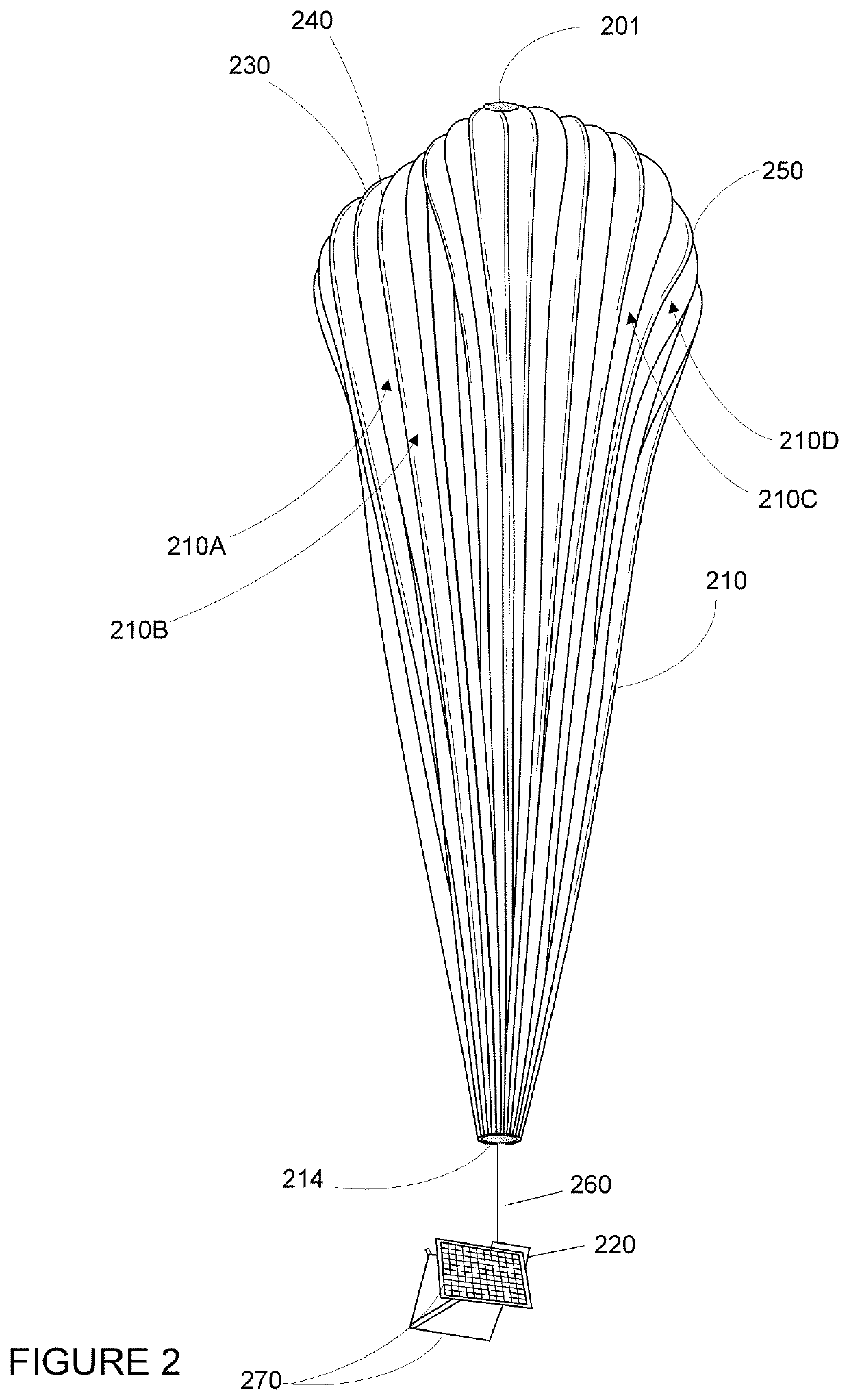
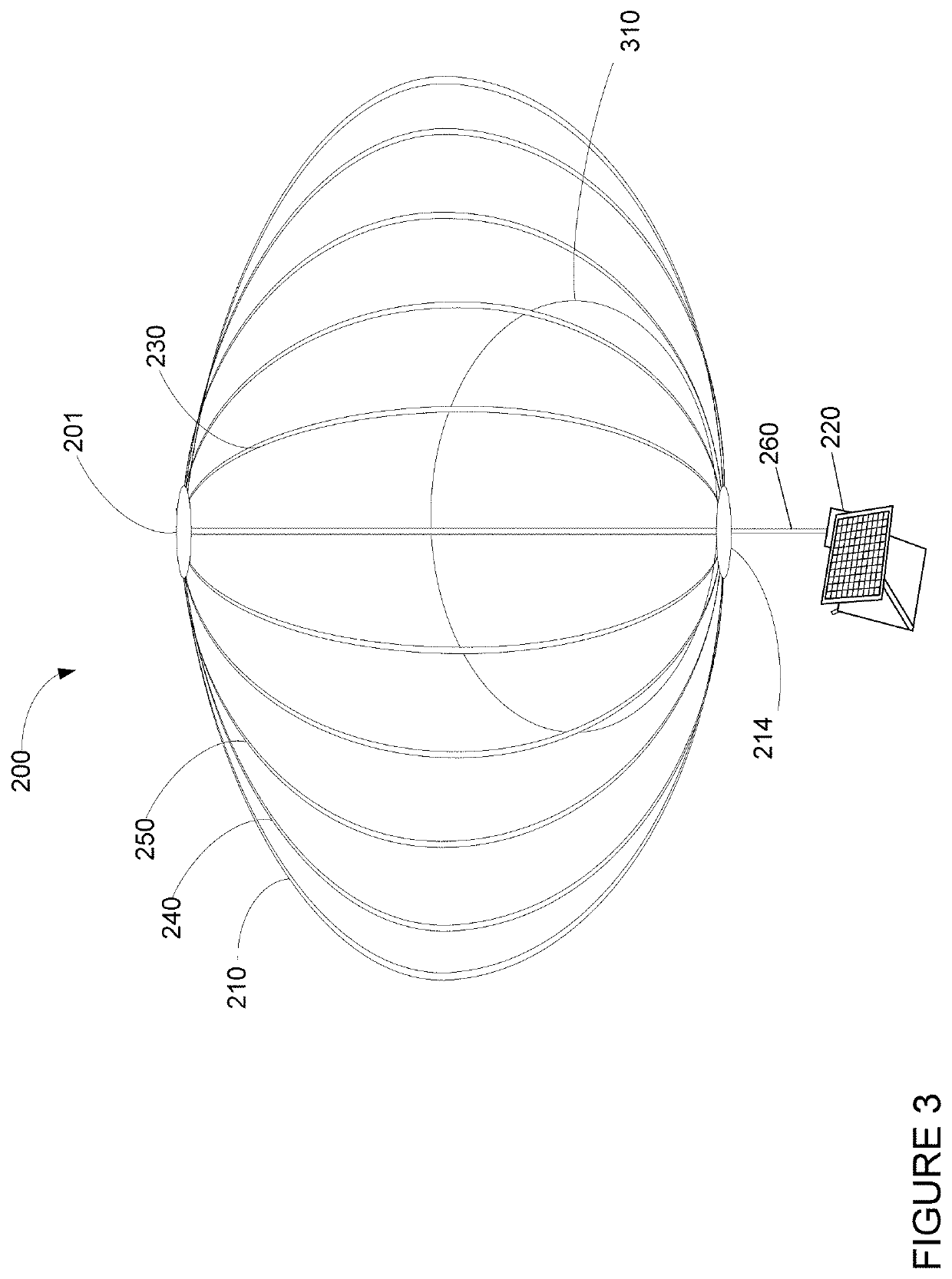
[0032]FIGS. 2 and 3 are examples of an aerial vehicle 200 which may correspond to HAP 110c, again, depicted here as a balloon. For ease of understanding, the relative sizes of and distances between aspects of the aerial vehicle 200 and ground surface, etc. are not to scale. As shown, the aerial vehicle 200 includes an envelope 210, a payload 220 and a plurality of tendons 230, 240 and 250 attached to the envelope 210. The envelope 210 may take various forms. In one instance, the envelope 210 may be constructed from materials (i.e. envelope material) such as polyethylene that do not hold much load while the aerial vehicle 200 is floating in the air during flight. Additionally, or alternatively, some or all of envelope 210 may be constructed from a highly flexible latex material or rubber material such as chloroprene. Other materials or combinations thereof may also be employed. Further, the shape and size of the envelope 210 may vary depending upon the particular implementation. Addi...

example flight termination

System

[0038]As noted above, in order to termination flight of an aerial vehicle, a flight termination system may be used. FIG. 4 is an example cross-sectional view of aspects of a flight termination system 400 and aerial vehicle 200. The flight termination system may include a heat source mounted on an aerial vehicle. For instance, as shown in FIG. 4, a parachute 430 and a heat source 410 may be mounted at a top plate 201 of the envelope 210 of the aerial vehicle 200. The heat source may be such that it is capable of melting an opening, represented by the area 440, in the envelope 210 using a fluid 412 such as hot air or other gasses. In fact, the heat source 410 may actually be able to melt through several layers of material, including, for example the envelope 210 as well as the ballonet 310.

[0039]As shown in the top-down view of FIG. 5, the flight termination system 400 may also include a second heat source 420 may also be used. In order to create a second opening in the envelope...


PUM


Abstract

Aspects of the disclosure relate to flight termination systems for aerial vehicles having envelopes. For instance, a flight termination system may include one or more heat sources mounted on the top plate and oriented towards envelope material of the envelope. The one or more heat sources may each include a gas generator configured to generate gas of sufficient temperature to melt the envelope material and vent lift gas from the envelope. The flight termination system may also include a drag device arranged at the top plate which may be being configured to provide stability to the envelope during descent.

Description

BACKGROUND[0001]Computing devices such as personal computers, laptop computers, tablet computers, cellular phones, and countless types of Internet-capable devices are increasingly prevalent in numerous aspects of modem life. As such, the demand for data connectivity via the Internet, cellular data networks, and other such networks, is growing. However, there are many areas of the world where data connectivity is still unavailable, or if available, is unreliable and / or costly. Accordingly, additional network infrastructure is desirable.[0002]Some systems may provide network access via a balloon network. Because of the various forces experienced by these balloons during deployment and operation, there is a balancing of needs between flexibility and stability of materials. As such, the balloons include a flexible envelope made of material that may be configured in sections or lobes to create a “pumpkin” or lobed envelope. These lobes are supported by a plurality of tendons. During norm...

Claims


Application Information

Patent Timeline
Patent Type & Authority Applications(United States)
IPC IPC(8): B64B1/62B64B1/48B64D1/12B64D17/80B64D17/62B64D17/28
CPCB64B1/62B64B1/48B64D1/12B64B1/06B64D17/62B64D17/28B64D17/80
Inventor BROOKES, KYLETRUSLOW, SAMUELBOUYGUES, LEONARDCROMIE, JOHN
Owner LOON LLC
Why Eureka
Try Eureka