Devices for the removal of clots

a technology of clot removal and clot removal, which is applied in the field of anchoring and retrieval of corpus, can solve the problems of threatening functionally, stroke is one of the most costly health problems, and sudden death of brain cells

Active Publication Date: 2022-01-25
AMNIS THERAPEUTICS
View PDF27 Cites 0 Cited by
  • Summary
  • Abstract
  • Description
  • Claims
  • Application Information

AI Technical Summary

Benefits of technology

[0034]Such arching forms a rounded configuration once the capturing unit is deformed, assisting in smooth retraction of the deformed units (with the captured corpus) into the catheter. Such smooth retraction also reduces the possible damage to the blood vessel during corpus capturing and retrieval.
[0073]The handling and manipulation apparatus (HMA) may comprise an actuator associated with a shaft pipe. As used herein the term shaft pipe denotes an elongated, typically tubular, element, which may be made of any material that can withstand or resist compression loads along the longitudinal axis, for example stainless steel. The shaft pipe typically has a longitudinal lumen, through which the guidewire is threaded. The shaft pipe may be fixedly coupled at its proximal end to the actuator via a shaft pipe handle, and at its distal end to one or more of the cylindrical bodies. The shaft handle on the actuator allows pushing or rotation of the shaft tube, thereby affecting the deformation of the capturing unit.

Problems solved by technology

A stroke event associated with a blood clot occurs as a result of disturbance in the blood vessels supplying blood to the brain, leading to sudden death of brain cells.
Furthermore, stroke is one of the most costly health problems in America and the Western world, with estimated direct and indirect costs of $38.6 billion annually.
The majority of the damage caused by a stroke is due to secondary stroke damage which threatens the functionally of the impaired region that surrounds the infarct core; the ischemic penumbra.
However, this treatment may increase the risk for intracranial hemorrhage and is currently not approved for use worldwide.
Beyond the failure rates of thrombolytic therapy, it is also limited in the time window for treatment and indicated population.
Such contact often causes additional damage to the blood vessel when the device is manipulated and moved within the vessel during the different stages of the procedure.
Further, in some configurations, the manner by which the device engages the clot may cause fragmentation of the clot, thus increasing the risk of emboli and necessitating the deployment of additional embolic protection elements / systems.

Method used


Image

  • Devices for the removal of clots
  • Devices for the removal of clots
  • Devices for the removal of clots

Examples


Embodiment Construction

[0099]As described above, the system of this disclosure includes a handling and manipulation apparatus (HMA) and a device operable thereby. The device is typically inserted into the vessel to be treated in a non-deformed (non-deployed) state via a pre-inserted catheter or micro-catheter. Once reaching the corpus to be extracted, the corpus capturing unit is deformed (deployed) for capturing and anchoring into the corpus, to enable its extraction from the vessel.

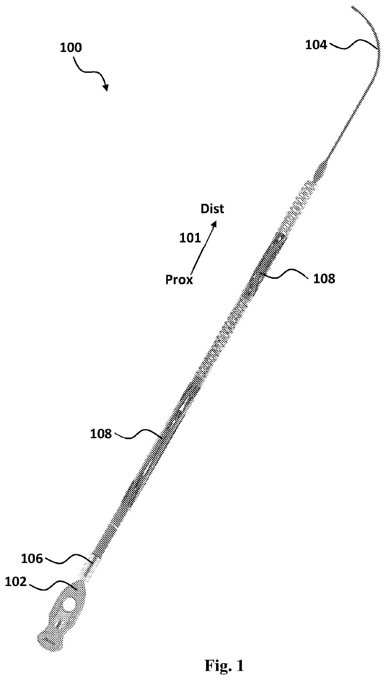
[0100]A device 100, shown in FIG. 1, is a generally elongated device extending in a generally proximal to distal direction (noted by arrow 101), from handling and manipulation apparatus 102 to a distal end 104. The device includes guidewire 106, a plurality of capturing units 108, each enveloping a distal portion of the guidewire. It should be noted that in other embodiments, the capturing unit can extend to envelop the guidewire substantially along its entire length. It is also of note that the HMA may have various designs (...


PUM


Abstract

Provided are medical devices, systems and methods for retrieval and / or extraction of a corpus located in a tubular organ. Systems of this disclosure are configured for carrying out various procedures for removal of occlusive corpus from tubular organs, for example thrombectomy.

Description

TECHNOLOGICAL FIELD[0001]The present disclosure relates to anchoring and retrieval of a corpus in an organ of a subject, in particular narrow tubular organs such as small blood vessels.BACKGROUND ART[0002]References considered to be relevant as background to the presently disclosed subject matter are listed below:[0003][1] Nogueira et al., AJNR 2009, 30, 649-661[0004][2] Grunwald et al. The American Journal of Neuroradiology 2011, 32, 238-243[0005][3] Mordasini et al. The eJournal of the European Society of minimally invasive Neurological Therapy, 2012: 1238000077[0006][4] U.S. Pat. No. 7,766,921[0007][5] U.S. Pat. No. 8,715,227[0008][6] U.S. Pat. No. 6,685,722[0009][7] WO 2013 / 054324[0010][8] Gralla et al., Am J Neuroradiol 2006, 27, 1357-1361[0011][9] WO 2011 / 130256[0012][10] Gory et al., Am J Neuroradiol 2013, 34, 2192-2198[0013][11] Levy et al., Am J Neuroradiol 2006, 27, 2069-2072[0014][12] WO 2017 / 072761[0015]Acknowledgement of the above references herein is not to be inferred...

Claims


Application Information

Patent Timeline
Patent Type & Authority Patents(United States)
IPC IPC(8): A61B17/221A61F2/01A61B17/00A61B17/22A61B90/00
CPCA61B17/221A61F2/013A61B2017/00004A61B2017/0088A61B2017/00292A61B2017/00778A61B2017/00809A61B2017/00818A61B2017/00862A61B2017/00867A61B2017/00893A61B2017/2212A61B2017/22044A61B2017/22051A61B2090/3966A61B2017/22034A61B2017/22035A61B2017/320064A61F2/01
Inventor SHAMAY, NOAMPLIS, RONEN ARIELSIRABELLA, EVYATARBUKAI, HADARKARNIBAD, MAYA
Owner AMNIS THERAPEUTICS
Why Eureka
Try Eureka